You won't achieve it any other way in a fully passive crossover design. If you're talking about the digital domain where pure delays are a piece of cake, that's a different story. (Although now the time alignment only applies on axis...)I agree, but i still don´t see the need to measure the time offset to get a time aligned system...
Build a "suitable" crossover and then add delays doesn't make any sense. Building a cross-over that phase tracks correctly with a specific time delay and then changing the time delay after the fact is going to completely screw up the phase tracking.My point is choose and build a suitable xover and then add whatever delays are necessary to get the best blend. Thats what do with the linear phasr FIR filters i use.
You have that backwards...decide on your time delay first (driver alignment and/or digital delay) then build your crossover...
You have that backwards...decide on your time delay first (driver alignment and/or digital delay) then build your crossover...
No, quite the other way. To get an optimal blend , never perfect, the right delay to be applied is xover dependant... with real world bandwith limited drivers.
Well, first define "optimal blend", thats a pretty vague target. Flattest amplitude response ? Least group delay ? Best phase tracking through the overlap region ?No, quite the other way. To get an optimal blend , never perfect, the right delay to be applied is xover dependant... with real world bandwith limited drivers.
Sounds a bit like you're taking a text book filter and applying delay until the phase tracking is close enough. If amplitude response flatness and phase tracking are the goals a specific delay isn't needed or optimal - just design the filter around the measured amplitude and phase curve to get the desired acoustic response, thats what most speaker designs do.
Whether amplitude response and phase tracking is enough is whats open for debate. (Eg does a gross delay between high and low frequencies matter, and if so how much is tolerable and in which direction)
Well, first define "optimal blend", thats a pretty vague target. Flattest amplitude response ? Least group delay ? Best phase tracking through the overlap region ?
Flattest amplitude response always comes first. The right delay is which allows the flatest amplitude response giving a "quasi time aligned" system. Perfect time alignment with flaws in the amplitude response is useless. That's why i don't bother with exact time alignment and precise offset measurement, and aplly delay empirically.
I agree, but i still don´t see the need to measure the time offset to get a time aligned system...
Flattest amplitude response always comes first. The right delay is which allows the flatest amplitude response giving a "quasi time aligned" system. Perfect time alignment with flaws in the amplitude response is useless. That's why i don't bother with exact time alignment and precise offset measurement, and aplly delay empirically.
These two comments seem a bit incongruous with each other. If your goal is to achieve "quasi time alignment" (not sure what that means) then how exactly would one apply delay "empirically" to achieve time alignment ? Surely you must measure something or its just guesswork ?
Let's take the case of a linear phase dsp based xover first. If my "guess" for delay is right the amplitude response will be flat enough and the system aprox. time aligned. Need more? If not, i have enough by tweaking the delay till i get both things acceptable. A piece of cake...
In the case of a passive xover, the result will never be linear phase so that i have little if any concern about time alignment, though i prefer shallow slopes with gentle group delay. Anyway, it doesn't matter, if i choose an LR24, i will tweak the delay for the flattest amplitude response, and will get the GD of a text book LR24. But i could also use an LR12 and need another delay, not necessarily the same as before, to get an acceptable amplitude response, this will depend on the drivers. I might also choose a1st order and try another delay but the choice of the drivers will be even more determinant for the result. Of course, if i used perfect drivers, all 3 delays should be the same, but drivers are drivers... And if i have no way to apply any delay, i would follow Speaker Dave's advices.
In the case of a passive xover, the result will never be linear phase so that i have little if any concern about time alignment, though i prefer shallow slopes with gentle group delay. Anyway, it doesn't matter, if i choose an LR24, i will tweak the delay for the flattest amplitude response, and will get the GD of a text book LR24. But i could also use an LR12 and need another delay, not necessarily the same as before, to get an acceptable amplitude response, this will depend on the drivers. I might also choose a1st order and try another delay but the choice of the drivers will be even more determinant for the result. Of course, if i used perfect drivers, all 3 delays should be the same, but drivers are drivers... And if i have no way to apply any delay, i would follow Speaker Dave's advices.
Last edited:
These distinctions show the differences between the active and the passive approach. For passive we try different slopes until phase overlaps. This amounts to achieving the same group delay for both sections for the overlap region. With active DSP you can hit the exact corner shape first then some availabe delay of one section or the other will give a classic LR combination and flat response.
David
David
A couple of questions on this:These distinctions show the differences between the active and the passive approach. For passive we try different slopes until phase overlaps. This amounts to achieving the same group delay for both sections for the overlap region. With active DSP you can hit the exact corner shape first then some availabe delay of one section or the other will give a classic LR combination and flat response.
1) If you are achieving phase overlap/tracking in a non time aligned design with a non-trivial amount of delay error even if you hit the right phase slopes to ensure "adequate" phase tracking through the overlap region, is it possible to achieve a flat summed response (ignoring driver response errors) or is there inevitably some amount of non flatness in the crossover region due to imperfect summation of unequal slope crossovers ? (If so how much ?)
Of course in a real design the drivers themselves may have more irregularities in response than the filter summation error, (so it could be moot) or if you get lucky or are clever the summation errors could complement the driver errors...
2) Such a system is obviously going to have a very different phase and group delay profile to a time aligned design using "classic" equal slope crossovers. Has any research been done on the audibility of un-equal slope (asymmetric) crossovers vs equal slope crossovers ? (Talking about the acoustic slopes here of course)
I'm not sure that studying the on axis summed response (frequency response, phase, group delay etc) is sufficient here either, as unequal slopes are going to influence the power response and spectrum of early reflections vs a time aligned equal slope design, when there are significant directivity differences in the two drivers...)
Last edited:
I'm not sure that studying the on axis summed response (frequency response, phase, group delay etc) is sufficient here either, as unequal slopes are going to influence the power response and spectrum of early reflections vs a time aligned equal slope design, when there are significant directivity differences in the two drivers...)
I agree, but what axis are we talking about?
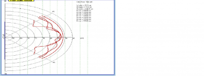
If we mount a classical 1' TW and a classical 7' W on a flat baffle with an LR design in mind, this is considered a non aligned system. Well, we should modify this statement because the drivers will not be aligned for an horizontal axis between the drivers, but you will always find an axis along which the drivers will be aligned, the only concern is that this axis might be badly tilting downwards, making the speaker difficult to use, but this axis exists and the amplitude response we measure on it is flat. The real problem is that the vertical polar response of this arrangement will be badly degraded compared with the one you get when the main lobe is horizontally flat.
If we then change the polarity of the tweeter, the result will be similar, but the new axis will be shifted upwards, and the polar response will be degraded compared to the ideal one, but in a different way.
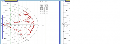
Anyway, by tweaking the slopes, for instance increasing the tweeter's side, the result will be bringing up ( or down with flipped polarities) the orientation of the main lobe, and the result will be a polar behaviour more conform to a textbook LR behaviour. The right amount of tweaking is the one which allows the closest match to the LR target, both on and off axis.
And of course, similar changes in the polar response can be obtained by applying delay.
Last edited:
A couple of questions on this:
1) If you are achieving phase overlap/tracking in a non time aligned design with a non-trivial amount of delay error even if you hit the right phase slopes to ensure "adequate" phase tracking through the overlap region, is it possible to achieve a flat summed response (ignoring driver response errors) or is there inevitably some amount of non flatness in the crossover region due to imperfect summation of unequal slope crossovers ? (If so how much ?)
It is certainly possible to have very flat response with this approach, but it will depend on what relative orders your pre-ordained delay wil require to work. As a best case you can end up with a near exact fit to the theoretical LR Butterworth squared targets.
I dont recall that many times when I needed strongly non symmetical slopes to get good allignment with passive crossovers. I suspect that the typical woofer-is-deeper geometry is more helpful here than the reverse would be.
You can also get decent summation with some time missalignment (phase curves that cross at an angle through the crossover region) with a little ripple. The issue is how far down the stop band side is relative to the phase error. But, yes, in the theoretical case of a pair of very nonsymmetric sections, even with perfect phase overlap the response won't be totally flat. I do think that normal passive network optimization tends to "make the best" of those cases.
2) Such a system is obviously going to have a very different phase and group delay profile to a time aligned design using "classic" equal slope crossovers. Has any research been done on the audibility of un-equal slope (asymmetric) crossovers vs equal slope crossovers ? (Talking about the acoustic slopes here of course)
I don't think this warrants separate research. Most of the studies I remember are either lumps of delay (Blauert and Laws) or steps in delay. (And systems can be a blend of the two.) Unequal rolloff rates would still fall into the "lumps of delay" category and would not be, in my oppinion, fundamentally different than their more symmetrical cousins.
I'm not sure that studying the on axis summed response (frequency response, phase, group delay etc) is sufficient here either, as unequal slopes are going to influence the power response and spectrum of early reflections vs a time aligned equal slope design, when there are significant directivity differences in the two drivers...)
You will be getting into pretty specific studies. I think any system that falls into the "approximately time alligned through the crossover" category will have symmetrical polars with up and down nulls. Do you think that systems with slightly different off axis holes can be generalized about (distinguished) in a typical study?
Look at Toole's measurements for typical power response holes at crossover. They have a general similarity from system to system and don't seem to cost the units anything in the rankings.
David S.
Precisely why it's such a simple task to determine relative acoustic offset with a 3-measurement approach. There is no ambiguity whatsoever. More interesting is that it is not even necessary to have measured phase with this approach. The summed magnitude response is a result of each individual driver's magnitude and phase. This summed response can only be achieved in CAD for design in two ways. By 1) using the direct measurements that include measured phase or 2) creating an accurate SPL magnitude model of each driver and generating phase. One other (theoretical) way is 3) knowing the absolute center of each driver.This method doesn't suffer from this limitation - we don't need to even look at the impulse at all (except to make sure the start marker isn't clipping the beginning of the impulse) and all the information needed to figure out the relative acoustic centre offsets is captured in the phase relationship of a single measurement.
Method 1 can be used, but at one point in space only for any software with which I am familiar, that being the measurement point.
Method 2 requires generating HBT phase somewhere along the way, so a reasonably accurate magnitude model is required. But once done, the model requires the baffle layout from which one then can easily determine the z-axis relative acoustic offset. The benefit to this is the ability to model any off-axis response (leaving diffraction out of the conversation).
Method 3 (a theoretical) is to take a measurement and subtract an amount of excess phase precisely equal to the distance from mic to driver, implying a known absolute center location.
Let me ask a question. What is the purpose? The discussion on group delay seems to be how to determine the absolute center of a driver. If one is focusing on each driver individually with excess phase removal for later comparison, there is no relative involved.
With that question comes another. How is the information to be used? If the actual direct measurements are used (for a single observation point) to design, then relative acoustic offset is moot. All phase, driver minimum phase plus all excess delay from drivers to the measurement point are included. There is no relative offset with which to be concerned. Case closed.
However, if the goal is NOT direct use of the measurements, not limited to a single point, you would import them into a software program so that a representative model can be created to either just investigate or maybe even design to other or multiple (as in averaging) points. Relative offset is required because you must use minimum phase results for the software to be accurate.
If group delay were to work for relative offset, unless I'm missing something somewhere, this is implicitly stating that the absolute center of each driver has been determined. How else would one determine the excess delay to remove?
My assumption is that a model must be created if you're not using direct measurements. This has to be either by knowing the absolute acoustic center to start with or by determining a relative offset. As discussed a bit above, we know that we cannot determine that to any reasonable degree of accuracy or so I still believe. So unless someone shows a method to do this, we are left with a relative method requirement.
In that case, how do design programs work? All of which I have used either use direct measurements or require a model from which HBT phase is extracted. The latter case eliminates all benefit of the excess delay method because the HBT depends solely on the SPL magnitude. You are dependent on the SPL magnitude models created. If in the end you're going to create a model, this comes full circle back to the use of three measurements. You create a model of each driver, find the relative offset for these specific models and you're done. There is no ambiguity as long as you don't alter the model later.
The moment that you try to use anything other than direct measurements, you are limited to generating HBT phase or so I believe. This invalidates the excess phase work because you're throwing away all measured phase at that point. If you import the result of excess phase removal, then this implies that the result is the precise minimum phase response which implies that the absolute center of each driver has been determined. I'm not convinced that this can be achieved using the method being described.
Dave
I think you are correct that any crossover simulation will either require direct measurement of phase or an HBT approach with some knowledge of acoustic center locations. In theory both should work just as well, but I was never happy with that aspect of LEAP (HBT requirement). I just found it too easy to make a mistake along the way and have yet something else to debug in terms of modeling errors.
I know that some have advocated summing sections together and just adding delay to one section or the other until the summed response looks right. I believe this works correctly, in theory, but why not just measure phase of all units from a fixed location?
Regards,
David S.
I know that some have advocated summing sections together and just adding delay to one section or the other until the summed response looks right. I believe this works correctly, in theory, but why not just measure phase of all units from a fixed location?
Regards,
David S.
Gentlemen
I just discovered your thread on time-delay and offer a free test signal on my website that you may find of interest . I developed this test for Altec 605As to optimize the low freq delay on a passive XO design. The test signal could be used with any multi way system. Play the test signal and turn on/off one the drivers ( LF, HF ) while observing the acoustic signal with a mic and scope.
http://web.me.com/donaldpatten
The test signal is after the schematic, key on with the small triangle.
Don
This will work fine for a single location. I've done that, it depends on the needs at the time.I think you are correct that any crossover simulation will either require direct measurement of phase or an HBT approach with some knowledge of acoustic center locations. In theory both should work just as well, but I was never happy with that aspect of LEAP (HBT requirement). I just found it too easy to make a mistake along the way and have yet something else to debug in terms of modeling errors.
I know that some have advocated summing sections together and just adding delay to one section or the other until the summed response looks right. I believe this works correctly, in theory, but why not just measure phase of all units from a fixed location?
I have a 2-way with a somewhat deep mid-bass unit. The response on the tweeter axis wasn't working out well. I decided to make the mid-woofer the design axis and now use it inverted (tweeter below). I could have either re-measured from the new axis or simply changed the design axis in the software having used a modeled response. If one has a modeled response, changes like this are trivial, though there may be some slight error due to off-axis measurements and directionality, though in my case it wasn't significant.
It's just a matter of choice. Either way can work just fine.
Dave
In a poor acoustic enrivonment, it might not be easy to set a sensible fixed location, and to avoid reflexions measurements might be done at 1m and even less. Those nearfield measurements might be ok for a small nearfield monitor, but for a bigger system intended for listening at 2, 3m or more, this way of measuring might introduce major biases.
I feel more confortable importing in a CAD soft measurments based on amplitude only, add hbt phase, piston diameters, offsets, distances and/or angles to build a model for simulation... and thus introduce other biases, but designing speakers in the kitchen has some price...
I feel more confortable importing in a CAD soft measurments based on amplitude only, add hbt phase, piston diameters, offsets, distances and/or angles to build a model for simulation... and thus introduce other biases, but designing speakers in the kitchen has some price...
There are a few ways to skin this particular cat, but, if working distance is a problem, I would still prefer to measure a meter in front of the woofer, a meter in front of the tweeter, then back off to a simulation distance with the arrival times corrected for that geometry.
My preference is to work with real phase curves and then subtract air transit time equal to the baffle distance. Tweeters will have a tiny bit of residual delay, woofers will have more delay, and I tell the simulator that they are all at Z = 0.
This works for me but others have their own approaches which are equally valid. (Off axis calculations would require real Z values.)
David S.
Gentlemen
I just discovered your thread on time-delay and offer a free test signal on my website that you may find of interest . I developed this test for Altec 605As to optimize the low freq delay on a passive XO design.
Don
Oooh, 10 element passive delay line. Hardcore!
David S.
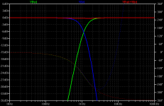
Yes, this is possible to high perfection.If you are achieving phase overlap/tracking in a non time aligned design with a non-trivial amount of delay error even if you hit the right phase slopes to ensure "adequate" phase tracking through the overlap region, is it possible to achieve a flat summed response (ignoring driver response errors) or is there inevitably some amount of non flatness in the crossover region due to imperfect summation of unequal slope crossovers ? (If so how much ?)
Below, assumed are acoustic LR4 responses, but the woofer being 200us ahead of the tweeter (like in a coax). An additional lowpass for the woofer can be always found that has just the right amount of group delay that cancels the time delay throughout the whole XO region with little impact on summed magnitude. In this case it was a 4th order low pass higher up that did the job, also the original LR4 targets need some fiddling/overlap. Overall spec is still that of a LR4 XO.
For the thread's question, the easiest and best DIY tool for most anything you'll ever need is HolmImpulse, you can do measurement, analysis and even synthesis (the latter with some external SW that calculates your filters).
Note that any driver can safely assumed to be minphase in the area of interest, that is, the XO area.
Attachments
Last edited:
The original topic was a method of measuring relative acoustic centre offset between two particular drivers in a single measurement. Perhaps the thread topic could have been worded a bit better but I think that intent is clear in my original post.Let me ask a question. What is the purpose? The discussion on group delay seems to be how to determine the absolute center of a driver. If one is focusing on each driver individually with excess phase removal for later comparison, there is no relative involved.
As you've pointed out previously an absolute measurement to a single driver is inherently going to have uncertainty that can't be avoided, however a relative measurement between two drivers when both drivers are measured summing together in the same measurement has the potential to be extremely accurate.
At the end of the day the relative delay is all that matters.
No relative offset ? Just because you might design the crossover to phase track through the overlap region doesn't mean there is no relative offset in the driver acoustic centres. Whether it matters or not is a separate discussion.With that question comes another. How is the information to be used? If the actual direct measurements are used (for a single observation point) to design, then relative acoustic offset is moot. All phase, driver minimum phase plus all excess delay from drivers to the measurement point are included. There is no relative offset with which to be concerned. Case closed.
You're really trying to over-think the situation here. Why is the absolute centre location of each required to determine the difference in delay of the two drivers ? It's not. The single measurement of both drivers crossed over with each other can tell you that. That was the whole point of my original post.However, if the goal is NOT direct use of the measurements, not limited to a single point, you would import them into a software program so that a representative model can be created to either just investigate or maybe even design to other or multiple (as in averaging) points. Relative offset is required because you must use minimum phase results for the software to be accurate.
If group delay were to work for relative offset, unless I'm missing something somewhere, this is implicitly stating that the absolute center of each driver has been determined. How else would one determine the excess delay to remove?
")
You seem to be seeing the discussion in this thread through the lens of "how does this help me using cad design software to model and design a speaker". Nowhere in my original post are there any assumptions about what will be done with the information, or that it would be used in any sort of cad software.My assumption is that a model must be created if you're not using direct measurements. This has to be either by knowing the absolute acoustic center to start with or by determining a relative offset. As discussed a bit above, we know that we cannot determine that to any reasonable degree of accuracy or so I still believe. So unless someone shows a method to do this, we are left with a relative method requirement.
In that case, how do design programs work? All of which I have used either use direct measurements or require a model from which HBT phase is extracted. The latter case eliminates all benefit of the excess delay method because the HBT depends solely on the SPL magnitude. You are dependent on the SPL magnitude models created. If in the end you're going to create a model, this comes full circle back to the use of three measurements. You create a model of each driver, find the relative offset for these specific models and you're done. There is no ambiguity as long as you don't alter the model later.
The moment that you try to use anything other than direct measurements, you are limited to generating HBT phase or so I believe. This invalidates the excess phase work because you're throwing away all measured phase at that point. If you import the result of excess phase removal, then this implies that the result is the precise minimum phase response which implies that the absolute center of each driver has been determined. I'm not convinced that this can be achieved using the method being described.
It's purely a way to measure relative acoustic offset between two drivers, something traditionally difficult to do very accurately, in what I thought was a reasonably novel and straightforward way.
(I haven't seen the method described before, and its only since the advent of highly accurate impulse based measurement systems that accurate measurement of excess group delay has become possible)
I think you're looking far too hard to see how it fits (or doesn't) into your particular cad based design workflow, rather than just accepting it for what it is - a method to measure the one particular parameter of relative z axis offset between two drivers, not to provide all the data you need to design a crossover.
Last edited:
- Status
- This old topic is closed. If you want to reopen this topic, contact a moderator using the "Report Post" button.
- Home
- Loudspeakers
- Multi-Way
- Measuring driver acoustic offset using excess group delay ?