
But what if I have 3 
You have to admit the easy to build compact shape is nice.
If you were to model these in WinISD you'll see strange curves. The Q is very low @ .22 Don't know why I ever bought one in the first place, other than a $19 sale price.
I did mock up a lot of boxes, changed volume; tuned them with temporarily clamped cabinets, shifting the the slot around to fine tune them. The impedance curve looked dead on to me, i.e. even peaks and valley @ 30hz.
The response is pretty darn flat from mid 30s to 100hz, which I always suspected by sweeping with generator and listening closely. I've made plenty of bad speakers so I know what one sounds like.
There was optimistic post about this box, scroll back to #110.
I'll post findings soon.
Aye,,,good idea, not going to work for some though.
Still have 3 of these, one is broken down; going to add plate amp.
A inherent problem with the tunnel is "ringing" which starts up around 100hz. Can not hear it once the xo is set at 80hz. that said, I wouldn't mind adding a layer of something inside the tunnel/rings.
Something similar to spray undercoating; but that takes about a year to dry.
Maybe something set in yellow glue: felt? cork?
Attachments
Hi ODougbo,
If you are still talking about the MCM 55-2421, I'm with BP1Fanatic on this one, the TH-SPUD is still one of the nicest for HT, and you could reduce the V_int from 281L to 150-190L. It's still going to be a large box, but at least it will get down low with authority.
Regards,
If you are still talking about the MCM 55-2421, I'm with BP1Fanatic on this one, the TH-SPUD is still one of the nicest for HT, and you could reduce the V_int from 281L to 150-190L. It's still going to be a large box, but at least it will get down low with authority.
Regards,
yes and sorry, I think some others got confused.
A friend brought over laptop/mic etc. and we measured the box shown above.
It looked good, not that I was surprised (well a little).
TH-SPUD...I'll see if I can find it.
I need to measure again, I think the program (free) was RTA? Any idea what that could have been?
btw...talked myself into cork (tunnel) and 1" fiberglass for walls (just a bit).
Last edited:
Hi ODougbo,
Sorry, I thought you were familiar with the TH-SPUD, Post #30 has the drawings, and Post #28 shows an internal picture (with way too much damping material for this sub); geitmans did a great job with this thread, it's worth taking the time and studying all of it:
http://www.diyaudio.com/forums/subwoofers/134369-dual-8-tapped-horn-th-spud-3.html
Regards,
Which one?
The Iso or the TH-SPUD?
I was thinking the Iso.
Which one is "better"?
But, let me warn you that I am fickle, and have starting thinking about either an open baffle or H or U frame instead.
Reason is that I am basically lazy, and they would be easier to build.
Randy
I was thinking the Iso.
Hi,
The MCM 55-2421 is totally unsuitable for isobaric use.
Its just very poor design, using a driver improperly.
rgds, sreten.
See : Silly's 1st Sub -- 8" MCM 55-2421
http://www.diyaudio.com/forums/subwoofers/80138-sillys-1st-sub-8-mcm-55-2421-a.html
Last edited:
Randy,
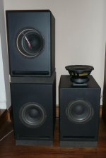
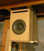
The Iso box shown works very well, it was not a one shot cabinet, I did build over a dozen prototypes. These two woofers in a small tight tunnel will give you nice clean bass; flat to 35hz, and down to 25hz.
This box was measured by one of the advanced member of this forum. (humble woodworker here)
We'll be taking a lot of flack (do you have bulletpoof vest?) on this but let me know if you need anything, could help out with the rings if needed.
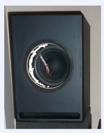
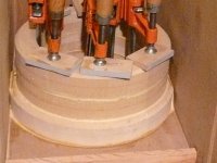
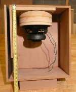
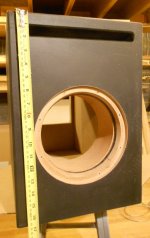
The pics are from different builds but the same idea:
pic 3 has the cork liner.
INSIDE DIMENSIONS:
17" deep
15" tall
9 - 3/4" wide (I call them the "rips").
The Iso box shown works very well, it was not a one shot cabinet, I did build over a dozen prototypes. These two woofers in a small tight tunnel will give you nice clean bass; flat to 35hz, and down to 25hz.
This box was measured by one of the advanced member of this forum. (humble woodworker here)
We'll be taking a lot of flack (do you have bulletpoof vest?) on this but let me know if you need anything, could help out with the rings if needed.
The pics are from different builds but the same idea:
pic 3 has the cork liner.
INSIDE DIMENSIONS:
17" deep
15" tall
9 - 3/4" wide (I call them the "rips").
Attachments
Didn't read up on the whole thread, but can you explain the reason why not configure the drivers magnet-to-magnet, please?
It should eliminate some unbalanced movement of the cones.
No need for a bullet prove vest from me, I used isobaric in my bandpass for years with good result!
It should eliminate some unbalanced movement of the cones.
No need for a bullet prove vest from me, I used isobaric in my bandpass for years with good result!
No to revisit every point on this thread, but this box has a very interesting impedance curve. I.e. the "peaks" are level and valley is 30hz. This is not easy; typically the first peak is difficult to bring up (with larger sized boxes).
@ Bart, interesting, but that also increases the surface area of the tunnel (where the cork is)
@ Bart, interesting, but that also increases the surface area of the tunnel (where the cork is)
Between the two drivers, there is a volume of air that moves back and forth with the cones, it does not act as a spring or resonance chamber.
My opinion is, that it is not necessary to line the inside, nor should there be felt or wool, on the contrary! There should be as little restriction as possible, meaning as wide as possible with a smooth surface.
Of course, this is just what I think of it. My isobaric drivers are facing each other, so there is a minimal volume between the drivers, which is, by the way, not something that is better or worse, I think your set up brings the resonance lower then my set up, since the mass is higher in your configuration(more air between the drivers means a higher mass).
You may have proof of concept, since you're the one doing all the hard work here.")
Interesting findings on the impedance. You say it has a valley at 30hz, what could that mean? That this is a frequency the box can't reproduce any-more?
My opinion is, that it is not necessary to line the inside, nor should there be felt or wool, on the contrary! There should be as little restriction as possible, meaning as wide as possible with a smooth surface.
Of course, this is just what I think of it. My isobaric drivers are facing each other, so there is a minimal volume between the drivers, which is, by the way, not something that is better or worse, I think your set up brings the resonance lower then my set up, since the mass is higher in your configuration(more air between the drivers means a higher mass).
You may have proof of concept, since you're the one doing all the hard work here.
Interesting findings on the impedance. You say it has a valley at 30hz, what could that mean? That this is a frequency the box can't reproduce any-more?
Last edited:
There are many on here that are well versed on tuning, but 30hz was the recommend box frequency by MCM engineers.
It is a simple, age old way to tune a box: amp, load resistor, generator, volt meter. The volt meter swings like a "M"; the low point is the box tuning.
The goal here: peaks are same voltage and low point is where you want, in this case, 30hz which is near the driver's Fs, 26hz.
It is a simple, age old way to tune a box: amp, load resistor, generator, volt meter. The volt meter swings like a "M"; the low point is the box tuning.
The goal here: peaks are same voltage and low point is where you want, in this case, 30hz which is near the driver's Fs, 26hz.
Interesting findings on the impedance. You say it has a valley at 30hz, what could that mean? That this is a frequency the box can't reproduce any-more?
- Status
- This old topic is closed. If you want to reopen this topic, contact a moderator using the "Report Post" button.
- Home
- Loudspeakers
- Subwoofers
- MCM 8" 55-2421 Isobaric