I thought I had posted this -- 2N5460 is available from Mouser. They have a couple hundred in stock.
I missed that, thanks! Well, on the other jfet I guess I go for the Chinese jfets and cross my fingers!
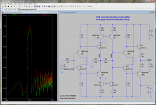
open loop performances of the DB-CM-DB architecture are quite amazing
Under simulation at any rate, my results bear this out 100%.
Attachments
Is there a compliment to the 2N2547?Update: I just purchased the 2n2547 jfets from Tayda2009 on ebay, since they have a good rep. After I get all the parts in, I'll report if I had any problems with matching or Idss.
Under simulation at any rate, my results bear this out 100%.
There is some gain there... Not optimized... should have lower distortion. Remove R6 and then it will be open-loop and then retest.
Is there a compliment to the 2N2547?
psst... Complement. You do this mistake in the article too.
Jan, note it for reprint
Is there a compliment to the 2N2547?
 It must be the day for typos. I meant 2N5457.
It seems that NTE457/NTE460 by NTE Electronics are equivalent to 2N5457/2N5460 - Newark has a few of them in stock.
L.
L.
It seems that NTE457/NTE460 by NTE Electronics are equivalent to 2N5457/2N5460 - Newark has a few of them in stock.
L.
Thx I'll get some and check them on the curve tracer to see how close they are to the ones I used. Got the ones i used very cheap on Internet (like, 12 cents). -RNM
Lots of devices will work on the front end -- but be mindful of the pinouts! I will try on Sunday. I have some sk170gr/j74gr matched up.
I have a lot of those types here - all sorted by Idss groups. Didnt want the high non-linear input C so I didnt try them. Let me know how it goes.
There is some gain there... Not optimized... should have lower distortion. Remove R6 and then it will be open-loop and then retest.
I interpreted "open loop" as "the output buffer is outside the feedback loop" rather than "there is no return current into the inverting input". I guess that was incorrect.
If you remove R6 completely however, things go a little screwy since the impedance of that node just jumps up to the remaining components surrounding it (Q13,Q14) - gain goes up (roughly 45 dB), distortion goes up, bandwidth goes down.
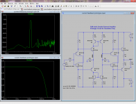
It is possible to run "open loop" by dismantling the feedback connection, connecting R6 to ground instead of R5. The simulated performance is largely unchanged.
Attachments
Last edited:
It is possible to run "open loop" by dismantling the feedback connection, connecting R6 to ground instead of R5. The simulated performance is largely unchanged.
Which is exactly the way my amp works
L.
I interpreted "open loop" as "the output buffer is outside the feedback loop" rather than "there is no return current into the inverting input". I guess that was incorrect.
If you remove R6 completely however, things go a little screwy since the impedance of that node just jumps up to the remaining components surrounding it (Q13,Q14) - gain goes up (roughly 45 dB), distortion goes up, bandwidth goes down.
It is possible to run "open loop" by dismantling the feedback connection, connecting R6 to ground instead of R5. The simulated performance is largely unchanged.
I'm not sure you are making progress here --- a lot more transistors/parts and worse thd/harmonic levels and dont know about offset and drift etc. No cigar. yet
psst... Complement. You do this mistake in the article too.
Jan, note it for reprint
yep. Compliment, for example, would mean to say something nice about you. Just another reason not to rely on the computers spell checker only. Thx
forr - I hadn't heard the term before, but on searching, it certainly seems to be a variant thereof.
coluke - and works it does, but I still don't understand why you'd choose that connection scheme (grounded) over the other (back to the front half of the current mirror). Seems to me like there is no difference.
rnmarsh - no, not yet. I'm not even sure what I should be "optimizing", even.
coluke - and works it does, but I still don't understand why you'd choose that connection scheme (grounded) over the other (back to the front half of the current mirror). Seems to me like there is no difference.
rnmarsh - no, not yet. I'm not even sure what I should be "optimizing", even.
Last edited:
rnmarsh - no, not yet. I'm not even sure what I should be "optimizing", even.
Here are my own modest base requirements for a line stage (similar for power amp):
1. Open loop BW of 40KHz or more (-3dB)... 20KHz min.
2. IM and THD of less than .001% at 1v rms into 30 ohms for any frequency between 20Hz and 20KHz.
3. No coupling caps on input or output or in feedback path.
4. No use of dc servo circuits to track and correct dc offset and drift.
5. No more than 6-8 transistors (excluding power supply).
6. S/N ref 1 volt rms and without weighting of at least -130dB (input can be shorted or terminated).
7. No significant harmonics above the 2nd and 3rd.
8. Closed loop gain between 12 and 20 dBv
9. Low Zout (less than a fraction of an Ohm at any audio freq).
10. Distortion not be changed by source Z.
11. Transistors should be low cost and not be exotic, hard to obtain, very expensive or no longer manufactured.
There might be a thing or two I missed, off the top of my head, but this is do-able and should be done in all audio circuits IMHO. -RNM
- Home
- Amplifiers
- Headphone Systems
- Marsh headphone amp from Linear Audio