Evening all ")
I'm half way through installing a Flea/Tentlabs XO clock, but something's got me confused...
Do I still need a +5v to pin 27 of the DAC - XVdd (Power Supply Xtal) if I'm using an external clock?
I assume not, but I can see people with external clocks who've left/upgraded CD04/CD05 caps in place which makes me doubt it..
Could someone confirm one way or another please?
thanks,
James
hmmm, I'm confused.
XTAL = Crystal, so it's literally the power to the original crystal, which I've just removed, which says to me it's useless now.
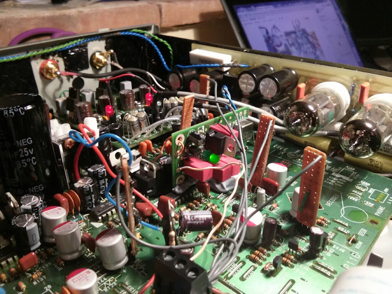
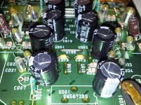
But then, here's an old picture of Ray's which shows a Flea clock and no original crystal, but with CD04 upgraded and moved to the CD05 position...

XTAL = Crystal, so it's literally the power to the original crystal, which I've just removed, which says to me it's useless now.
But then, here's an old picture of Ray's which shows a Flea clock and no original crystal, but with CD04 upgraded and moved to the CD05 position...
ok, well I have the answer now. You definitely need it. Won't play without it, but give it 5v and it's all happy.
Just hearing the new improved clarity from the Flea/XO clock for the first time and I'm very happy with the improvement
Now it's time to rip it all apart and have a go at installing the DOS board too....
Just hearing the new improved clarity from the Flea/XO clock for the first time and I'm very happy with the improvement
Now it's time to rip it all apart and have a go at installing the DOS board too....
OH MY WORD, that sounds nice 
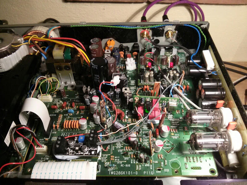
I'm still waiting on some 12v shunt regs for the DOS board, so I'm running it on a 7812 and 7912 for now and the flea clock is just going to the DAC and is plonked in mounted on blutack, but my word, I'm happy with that
I'm using the first part of Ray's CFP DOS board to sum the signals from the DAC properly, but I'm then diverting out and using my Valve SRPP output stage.
It was one of those where it should work in theory, but until you hear the lovely music you're never sure. But it's just fired up first time and it just sounds glorious
It's taken me bloody ages to get to this stage and still needs a bit of tidying and such, but I can see the end in sight and I'm a very happy guy just now
Here's some pics:
Thanks all for your help, especially Ray
50va tx
Hi,
fh11/12 are the fuse holders which ive removed for the new tx input to create a symetrical supply does fh 11 u308 have vsec u309 is 0v and u310 become the negative supply ie 0v to u310 and vsec to u309.
thx alan
Alan, I'm certain that 12v +- regs for the servos are fine. I think that's what Brent has in his recommended list iirc.
Not sure what you mean about problem with the Fuse holders, but I'll have mine apart this evening to fit Ray's DOS board, so just shout if you want any pictures or measurements
Hi,
fh11/12 are the fuse holders which ive removed for the new tx input to create a symetrical supply does fh 11 u308 have vsec u309 is 0v and u310 become the negative supply ie 0v to u310 and vsec to u309.
thx alan
Last edited:
Hi,
fh11/12 are the fuse holders which ive removed for the new tx input to create a symetrical supply does fh 11 u308 have vsec u309 is 0v and u310 become the negative supply ie 0v to u310 and vsec to u309.
thx alan

That's the info for my tx and that's the order I have them in, with the centre 2 going to ground u309 which runs between the 2 fuse holders. I drilled a couple of small holes between the fuse holders either side of the trace that runs to u309s, so it's
FH11 - vsec
GND/u309 - 0v
GND/u309 - vsec
FH12 - 0v
Does that make sense?
I think the short version of the reply is "yes, it looks like you have it planned correctly
"
Last edited:
tx
Thx thats as i thought,what are your impressions on this mod? I will post some pics as soon as im done.
thank you alan
That's the info for my tx and that's the order I have them in, with the centre 2 going to ground u309 which runs between the 2 fuse holders. I drilled a couple of small holes between the fuse holders either side of the trace that runs to u309s, so it's
FH11 - vsec
GND/u309 - 0v
GND/u309 - vsec
FH12 - 0v
Does that make sense?
I think the short version of the reply is "yes, it looks like you have it planned correctly
Thx thats as i thought,what are your impressions on this mod? I will post some pics as soon as im done.
thank you alan
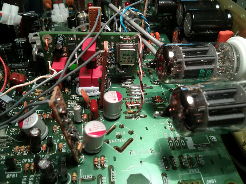
I fixed the legs on T5 and the DOS works! Thanks for posting the schematic with the voltages about a million years ago, Ray!
While swapping over I was surprised to find that the player still works with the op-amps removed - just very quietly.
I haven't had a chance to listen properly yet because it was late when I finished. There is very noisy mains hum compared to the op-amp stage, but it's only hacked in with long wires running from the DAC pins to the DOS board so I'm hoping it'll get quieter once it's fitted properly.
Anyway, exciting to finally have it working! Assuming I can fix the hum, all it needs now is better metal foil resistors and better regs (it's on 2x 7812 & 7912)
So I guess this answers the question about how to provide a clock signal direct to the decoder on a v1 cd63
Also, have an arty evening shot of the glowing goodness.
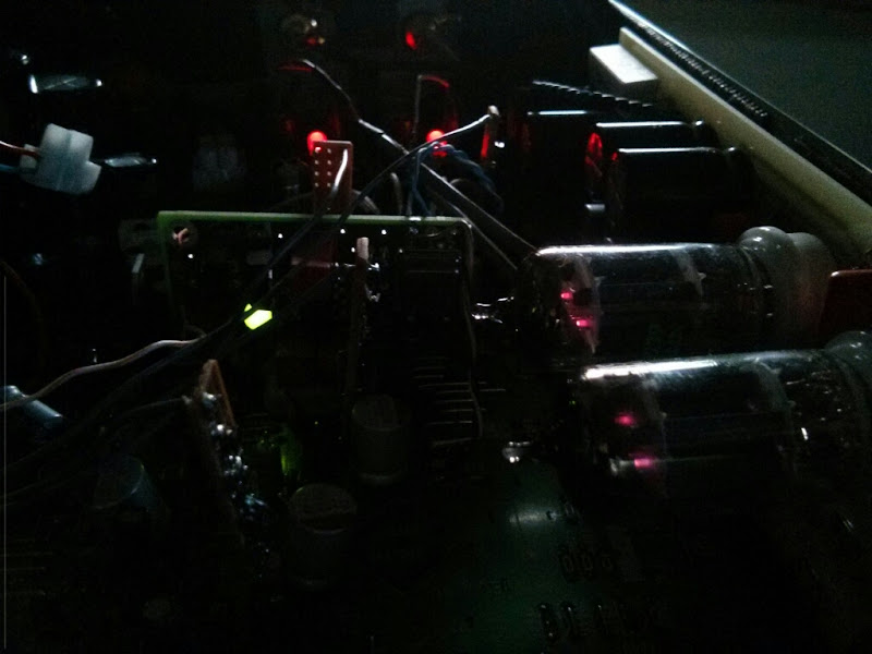
It's getting pretty busy in there now... All I have left to do is to fit a clock divider and give 8mhz to the servo, mount the clock properly instead of blutack and to fit some better 12v shunt regulators to the DOS board. Then a quick tidy up and I think I'm done!
Also, have an arty evening shot of the glowing goodness.
It's getting pretty busy in there now... All I have left to do is to fit a clock divider and give 8mhz to the servo, mount the clock properly instead of blutack and to fit some better 12v shunt regulators to the DOS board. Then a quick tidy up and I think I'm done!
Question for you DOS guys: How do you have your RCA sockets grounded? Mine are still wired to the original star point where the stock socket was connected. Should I run twisted pairs from the DOS instead?
It's best to use isolated RCA sockets and connect the grounds to the output-side of the DOS board. The DOS generates the signal, so that is the source the grounds should be connected to. The DOS board is connected to the ground of the player at the input side and through the power-supply.
The original star-point is no longer useful if the opamps aren't used.
Ray
Hi Ray, thanks for your reply. The bad news is I got your message too late, but the good news is I did exactly what you advised anyway! I've just finished hooking it up properly and it's sounding wonderful. I found it really daunting to go back to the board once I found it didn't work all those months ago. That Mundorf silver solder on a high quality through-hole board like this is not an easy medium in which to undo mistakes. I'm so glad it was just the two transistors, and I happened to have another pair.
Tip for future DOS installers: I recommend using solid core, colour-coded hookup wire to connect the board to the DAC.
Tip for future DOS installers: I recommend using solid core, colour-coded hookup wire to connect the board to the DAC.
Tell me about it! I had to take my faulty LM317/337 regs out of my DOS when they didn't work properly....That Mundorf silver solder on a high quality through-hole board like this is not an easy medium in which to undo mistakes.
When I swap the current 7812/7912 regs out for something better, I'm definitely just snipping them off and removing the legs individually
- Home
- Source & Line
- Digital Source
- Marantz CD63 & CD67 mods list