We're good. I wasn't really taking it at all personally. I was just poking my head above the earthenworks looking for barbarians! Seriously though, never doubt your ears and ignore what the brain says. And I was being serious about there being people who think we are delusional...never mind cable directionality etc. Mercifully this thread leads a charmed life and we are all true believers. Some, like me, live on the edge and go for hard-core stuff like no fuses, ebony cones, lead sheeting, after-market power cords, and not to forget Lexan tops! I admit to being greedy and excessive (and totally useless with a soldering gun and a circuit diagram...hence our very own Rowmeister, who had gone where no man has ever dared)
only the very clever or very rich will get it.
Not entirely true. I'm not clever and anything but rich, quite the opposite. I am, however, close to my nirvana. I have a sound I like a lot and could only dream about a few years ago.
Perseverance is key!
Simon
A hint of rapture from Simon! I'm having a hard time getting the Lexan top and the wood cheeks to fit. Turns out the Marantz casework is anything but "true". Photos should be this week sometime, when the wood has been sanded and stained and has a good wax finish. Looks pretty smart I must say, even now.
Last edited:
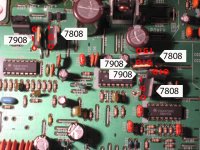
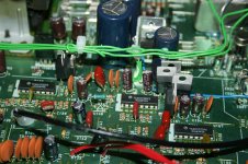
Hi guys, got the part from Farnell and did some more modding esp. to the power section (the big panasonics caps) and the decoupeling caps for the drivers (C153,154 C135,136 & C146148). The bass is now quite allright, but still got problems with the flat sound I mentioned before. After putting in the 8v regs at the driver ic's the magic was gone. Even now with the lm4562 in place there's no air, depth and it sounds lifeless. So maybe I did something wrong?
Can anybody please check if I did install the 8v regs the right way? There seems to be a difference between my picture (on the left, before putting in the new caps btw) and Brent's. Can't figure out what I did wrong though (I put the output towards the ic's)
Tnks!
Can anybody please check if I did install the 8v regs the right way? There seems to be a difference between my picture (on the left, before putting in the new caps btw) and Brent's. Can't figure out what I did wrong though (I put the output towards the ic's)
Tnks!
Attachments
Then remove the TX and replace it with a 50Va 2x 12V. You will also have to add a small tx for the display.
Brent
Hi Brent, how (where) do you connect the 2 new tx to the pcb?
Regards
Pete
Hi Brent, how (where) do you connect the 2 new tx to the pcb?
Regards
Pete
Sorry, might have misread the original mail, is this just if you're using the player as a transport only?
You can do this whether it's a transport only model or standard cdp.
On say a KI remove the TX and replace it with a 50Va 2x12V tx and connect ot down to the correct ac inputs on the pcb (red blue and yellow). Find somewhere for a 30VA 2x 15V tx for the analogue psu and a 1.6va 2x 12v tx for the display with a dropper resistor to get the tube volts correct.
You can see the setup on my pdf - page 12 for the display and servo bit
http://www.fidelityaudio.co.uk/rmcdmodlist.pdf
Brent
so..
The 15v connects into U306, U307 with centre tap to U309 ?
The 12v connects into U308, U310 with centre tap to U309 ?
The display tx connects into U311, U312 ?
What connects into U305?
Sorry for the step by step questions but there's potential for a lot of smoke (and maybe some flames ) if I get this wrong.
Thanks
Pete
The 15v connects into U306, U307 with centre tap to U309 ?
The 12v connects into U308, U310 with centre tap to U309 ?
The display tx connects into U311, U312 ?
What connects into U305?
Sorry for the step by step questions but there's potential for a lot of smoke (and maybe some flames
) if I get this wrong.Thanks
Pete
so..
The 15v connects into U306, U307 with centre tap to U309 ?
The 12v connects into U308, U310 with centre tap to U309 ?
The display tx connects into U311, U312 ?
What connects into U305?
Sorry for the step by step questions but there's potential for a lot of smoke (and maybe some flames
Thanks
Pete
Yes to all those, the spare 12v on the 3.6va tx connects to there and and gnd (U309) You can use U267 instead of U305 if you want. Remember to add the resistor between the tx and U305/U267.
Brent
Ian,I'd go for whatever VA you can without getting loads more expensive.
The 7va version of that encapsulated is only about 50p more again. The only trouble with those tx's is that they are better mounted on a pcb (veroboard is fine). If you are mounting free, its better to use an open torroid (not the RS value ones as they dont come with the mounting plates).
I saw you added those big caps and got the balance back!!! ;-)
I did buy an open type 7va tx ,Whats not too clear is the dac conections, you said remove u 196 to isolate pin from clock and also u165 and feed 16.934mhz in the pin closest to the dac and cut trace to pin 1 this ok.
thanks ian

Hey Shepperd.
The improvement of changing from a C1 and C2 is pretty big. The C2 is a much more complex and well-designed product, having on-board low noise regulation and a logic circuit which divides and buffers the output.
This lets you clock the various chips direct, resulting in better isolation/cross-polution of the delicate clock signal.
You get much better sound from this: better bass, separation of musical textures and better dynamics to the music too. I've upgraded several players from c1's to c2's now and have had the same results every single time.
Cheers, Lee.
Shepperd has a CD67, though, so won't see all those benefits to the maximum extent.
When I upgraded from C1 to C2 I first tried it in place of C1 doing the same tasks and it was quite clearly superior. The sound was warmer and more controlled and clearer. Later, I reclocked further circuits using the dividers and got superb results.
When I upgraded from C1 to C2 I first tried it in place of C1 doing the same tasks and it was quite clearly superior. The sound was warmer and more controlled and clearer. Later, I reclocked further circuits using the dividers and got superb results.
- Home
- Source & Line
- Digital Source
- Marantz CD63 & CD67 mods list