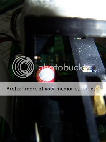
rowemeister said:The CPU is the big black rectangular ic (QF01) and the cap in question is CF02
Brent
Noted, thanks Brent.
Do u have any idea on my question on pcb under the transport mechanism changes.. now its not reading and sometimes not function properly.
Could it be a polarity problem with the ecap change ..?
Regards,
Marcus
marcusdeming said:
Noted, thanks Brent.
Do u have any idea on my question on pcb under the transport mechanism changes.. now its not reading and sometimes not function properly.
Could it be a polarity problem with the ecap change ..?
Regards,
Marcus
I don't think so, unless a cap has blown up (you'd probably know about this if it happened). When mine decides to stop working it's usually because I've lifted a pad or even not soldered something properly.
I'd imagine you'll have to look over every part you've changed very carefully and also look for areas where you may have accidentally bridged two areas together with solder.
The polarity of the e-caps is usually easy to check as the psus are mostly +5v rails, therefore the ground of the cdp needs to be in contact with the negative side of the cap (the banded side). If you have a multimeter with an audible continuity beep this will help a lot in finding shorts and quickly determining whether the caps are in the correct way round.
If your player doesn't work, you could try starting it in "service mode". This will give you an error code, which can be checked against a key in the service manual. Err02, for example, is a servo error.
I think to access service mode, you turn the power on with play and stop pressed in at the same time. If not, you'll have to check the service manual for how it's done.
Regards,
Simon
SimontY said:
I don't think so, unless a cap has blown up (you'd probably know about this if it happened). When mine decides to stop working it's usually because I've lifted a pad or even not soldered something properly.
The polarity of the e-caps is usually easy to check as the psus are mostly +5v rails, therefore the ground of the cdp needs to be in contact with the negative side of the cap (the banded side). If you have a multimeter with an audible continuity beep this will help a lot in finding shorts and quickly determining whether the caps are in the correct way round.
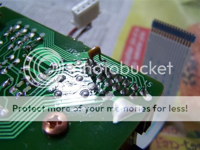
Thanks Simon, i do think that some of the pads are a little damage by me, but i am unsure whether if my polarity is right at the transport pcb section, not sure if u can see. the tape is flat tape cable is on the left and the -ve side of my ecaps is facing it.
How about the 100n x7r attached on the J102, did i do it correctly, because i am not sure how its counted
SimontY said:
I'd imagine you'll have to look over every part you've changed very carefully and also look for areas where you may have accidentally bridged two areas together with solder.
If your player doesn't work, you could try starting it in "service mode". This will give you an error code, which can be checked against a key in the service manual. Err02, for example, is a servo error.
what are the things i can do it say the pads are damage?
The places that i think looked badly solder are those with the 100npps soldered at the bottom of some of the ecaps at the DAC and opamp area. could this be a problem ? The PPS are not lying flat like what shown in Ray's picture.
SimontY said:
I think to access service mode, you turn the power on with play and stop pressed in at the same time. If not, you'll have to check the service manual for how it's done.
Regards,
Simon
Thanks i didnt know about this. what happened if there is multiple error..
Lastly, i also did the small mod according to acoustica, connecting a 100nx7r across pin 2 and pin 27 on the DAC and scraping the trace below pin 2. When cutting trace, do we scrape it till we see some brown patch..?
Regards,Marcus
marcusdeming said:
Noted, thanks Brent.
Do u have any idea on my question on pcb under the transport mechanism changes.. now its not reading and sometimes not function properly.
Could it be a polarity problem with the ecap change ..?
Regards,
Marcus
What is the big cap fitted under the transport?
This is not normal, changing any cap values on this pcb with a delicate signal will most defo cause problems.
The X7 cap is also across LD to gnd (pin 4 and 5) , lift one leg and try. I assume the electrolytic is the problem
Brent
rowemeister said:Talking about downgrading. I may sell my stuff and get what these guys have, coin in the bank then
Downgraded audio
Brent
hahahah lol, now that is truly sad. Couldn't stop laughing at the guy when he used some anti-static gun in mid air just before putting that custom made ring down onto the turntable
HAPPY NEW YEAR EVERYONE.
Just a little question about cap leg lengths. In my headphone amp ive had to lift the BG's i installed up and tilt them so they can actually fit. The legs are now 10-15mm above the PCB. Will that have any noticable effects as to stand them upright i need to cut the top of the case and have them sticking out ???
................ and before you ask, yes that amp is a bit dead too. But it came like that and wasn't my doing. When ever i plug my headphones in there is a hum in one channel, then the music plays through my headphones at a volume that would probably blow them if left for too long.
Hi Marcus,
I've not followed your modes from the begining but I thing I faced the same problem with my CD57.What I found was that if you replace the resistors with coils that have a DC resistance bigger than the resistor they replace the transport can not focus(err02).
I do not have the knowledge to explain this but that was my experience.Hope this helps.
Mik
mikvous said:Hi Marcus,
I've not followed your modes from the begining but I thing I faced the same problem with my CD57.What I found was that if you replace the resistors with coils that have a DC resistance bigger than the resistor they replace the transport can not focus(err02).
I do not have the knowledge to explain this but that was my experience.Hope this helps.
Mik
It would cause too large a voltage sag and, as Brent has told me before, the player does not function correctly when the voltages drop too low. You need to check the resistance of your inductors/coils/chokes where you have used them to replace power supply resistors.
Simon
avr300 said:Just upgraded my Raygulators til Super-Raygulators
Thanks to Martin at http://www.acoustica.org.uk/
Hi avr300,
Could you please tell me part no.s for the Gyrator? and Zener Diodes for this. Was about to make some Raygulators (for which there are a number of details for Caps and resistors, e.g. Eddie Wang's Site) and then I read the Acoustica spiel on these, and how they could be better with Two Zeners i.e. "Putting two zener diodes in parallel in place of R2".
Now, Eddie Wang's site http://eddie.dyec.com.tw/diy-products/vrm/vrm.htm lists
3V R1=100 ohm R2=140ohm
5V R1=100 ohm R2=300ohm
12V R1=100ohm R2=860ohm
15V R1=100ohm R2=1.1Kohm
I'm learning here, but I guess if it is just the R1/R2 RATIO that sets the Output Voltage, you could choose any pair that gives the correct ratio. So what did you choose? The only qualifier from Martin is to "make Z (the impedance) of C2 much smaller than R2 at twice your AC Mains frequency to suppress ripple better; 100uF will be more effective than 10uF."
If R2 is for a +5V reg or a -12V/+12V reg, what is the equivalent Zener for that application?
btw what is the "Gyrator". I didn't see that on Acoustica's Page for http://www.acoustica.org.uk/t/3pin_reg_notes1.html???
k.
Slightly Off-Topic
Speaking of regulators, I upgraded my preamp over Christmas to use Brent's delightful new S-Power regs. +/- 15vdc.
I will be using a pair to power the output stage of my CD63 as soon as I can afford it.
Terrific all-round gains and really musical and dynamic. More detail and better imaging, texture of instruments, speed and depth of bass. Overall there's a sense of calm and ease that was missing previously. Cheap regs seem to be a false economy!
Pre-reg caps are 2200u Nichicon, post-regs are 220u Cerafine. Bypass are 1u polyester. Diodes are schottky. Preamp is 2 x LM4562. The 15000u were connected for a bit but I disconned them trying to isolate a problem, not sure about their addition pre-regs.
Simon
Attachments
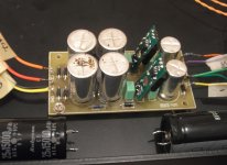
rowemeister said:Nice to see my babies in situe
Brent
Free samples program ????????
i promise not to break your babies
adfinni said:Free samples program ????????
Hahaha, I wish. I still owe him!! They're well worth the money though!!
rowemeister said:Nice to see my babies in situe
Brent
Looks nice indeed Brent, but as i'm a real dutch guy: ~ 62 euro is a bit pricey though! Is there is discount for us DIY'ers
??Ray
rowemeister said:Don't worry about the X7R for now. Try the E cap first and see what happens.
Brent
Hi Brent and all,
I have replaced the parts back, and removed the 100n X7R on the small PCB on the transport.
Previously, I had replaced the C107 with the Cerafine caps and also added the 100n x7r in between pins 4 & 5. As I had some spares, I also changed the caps on C106 from a 10uf/25v to a silmic 10Uf/35v.
My CDP is still not reading my CDs.
I have also tried to start in the service mode, and it shows an error 12 - which is the SLED.
I also noticed that one of the pads for the pins of C106 is peeling off. What can I do about this?
6h5c said:
Looks nice indeed Brent, but as i'm a real dutch guy: ~ 62 euro is a bit pricey though! Is there is discount for us DIY'ers
Ray
Im sure I could do them a little cheaper for members, my problem is volume and the costs with low volumes are high
. Brent
- Home
- Source & Line
- Digital Source
- Marantz CD63 & CD67 mods list