marcusdeming said:I don't quite get it, do u have a picture of it.
Yes, plenty of pictures: www.raylectronics.nl

Ray
Some of the mods which I have done till now.

bypass hdam with wire, jumper R651-654
Do I need to jumper C651-654?
I have also removed the headphone circuit C901/902 and also jumper U271/272. Muting circuit 24/25/91/92 and RN27/28 are also removed. Jumper at U207, U211 & U262 (cut trace) are also removed. However, I do not understand the instructions saying "decouple each muting line to ground with 200n/x7r at junction U222/223 and output site to remove noise".
Does it mean that I will use a total of 4 100n/x7r from the holes pointed to the copper strip in the centre? Currently, the U222 and U223 are on jumper. Does it mean that I will have to remove them and insert the 100n/x7r here as well? Thanks!
dc blocking caps
Hi Guys. New to the thread and I've learnt loads from it - I can't believe how much knowledge you guys have!
I've been searching through since the middle of the evening and it's now gone 5am!
Can anyone please tell me the references for the DC blocking caps and if I can just remove them without jumpering?
I'm afraid I'm very new to modding and I don't want to screw up.
Also I'm following Ray's mods list using Elna RJH around the decoder with 100n Panasonic PPS underneath the board between the leads. Does the polarity matter here for either of the new caps?
I'd really appreciate any help you could give.
Thanks guys.
Gentlemen,
I have been sitting back for a while enjoying the sound of the modded player. I have also been building some room treatment and have upgraded my interconnects with Eichmann Bullet Plugs.
It's now time again to risk ruin and do some further mods. This will include replacing a lot of capacitors with Black Gates.
I was hoping one (or more) of the more experienced knowledgable tweakers could provide a 'paint by numbers' list of instructions for the coax mod for we the lesser people for a 63 KI sig MkII. This would include any changes to existing components (i.e. resistors, capacitors etc).
My hope is to make the post a reference for other modders (and for my own selfish reasons of course") ).
).
Thanking you greatly in advance,
Simon
I have been sitting back for a while enjoying the sound of the modded player. I have also been building some room treatment and have upgraded my interconnects with Eichmann Bullet Plugs.
It's now time again to risk ruin and do some further mods. This will include replacing a lot of capacitors with Black Gates.
I was hoping one (or more) of the more experienced knowledgable tweakers could provide a 'paint by numbers' list of instructions for the coax mod for we the lesser people for a 63 KI sig MkII. This would include any changes to existing components (i.e. resistors, capacitors etc).
My hope is to make the post a reference for other modders (and for my own selfish reasons of course
).Thanking you greatly in advance,
Simon
Morning guys.
Just found the answer to my question on polarity - sorry, gave up two pages from the end last night but still need to know the DC blocking caps refs,
Hi Simon
Just read your post. I second that emotion on the coax mods. Have you seen Brent's mods on this link from the previous page
http://www.eurolinkcourses.co.uk/si...D63 KI MODS.rar ?
I am new to modding, fairly handy with a soldering iron and can recognise components but not much understanding of why the circuits work.
All I do know for sure is that my main reason for all the work is to end up with great sound and then enjoy it!!
All the best for 2007 to tweakers everywhere!!!
Jim
Hi Jim,
I've read Brent's very useful document. I feel confident to follow the instructions, but less confident to 'disconnect/peel off' the original copper circuit and would appreciate more information on that.
Plus it would be useful to know (preferrably by pictures) where to ground the shielding on the coax cables.
Simon
Can anyone please tell me the references for the DC blocking caps and if I can just remove them without jumpering?
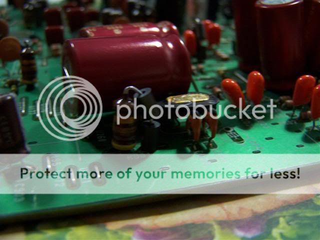
Hi JimH, the DC blocking caps are the two 220uf capacitors in series behind each of the HDAM cans at the rear, there are two capacitors on each of the channels.
You need to jumper these out if you are using the output to the present RCA connectors. If you are completing other mods such as taking your output before the HDAM (whilst isolating it) to new RCA's it wont matter.
Sorry im in the office and not got the circuit.
http://www.diyaudio.com/forums/showthread.php?postid=932612#post932612
This show how I bypassed my DC blocking caps.
This show how I bypassed my DC blocking caps.
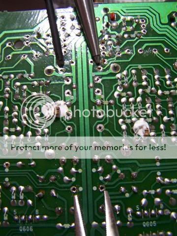
Can someone pls shed some light on the question i ask ealier regarding the jumpering U222/223 with a 100n x7r according to the Ray's mod list.
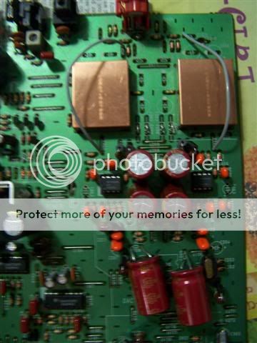
Posted some pictures of my progress...
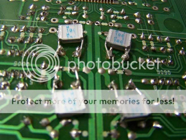
The 100nx7r on the bottom of the power supply area as mentioned in Ray's mod list.

The 100nPPS, not sure if i got the right stuff, i got them from a surplus electronic store. These are soldered underneath the opamp ecaps.
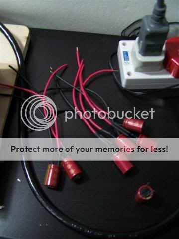
Some of the other mods according to Ray's list on the output filter, can someone assist me in verifying the parts, i replace the mylar(ornage bob) with some mica(values as indicated in the mod list). I am rather skeptical about the bluish bob on L601/602 as shown in my picture, not sure if i was given the right parts.
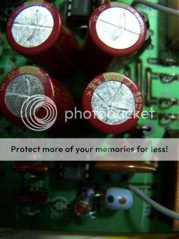


Many thanks in advance for any help rendered, i have yet to power it to see if it works, as awaiting some more parts to arrive, before soldering in some big caps to be attached by wires.
Regards,
Marcus
Posted some pictures of my progress...
The 100nx7r on the bottom of the power supply area as mentioned in Ray's mod list.
The 100nPPS, not sure if i got the right stuff, i got them from a surplus electronic store. These are soldered underneath the opamp ecaps.
Some of the other mods according to Ray's list on the output filter, can someone assist me in verifying the parts, i replace the mylar(ornage bob) with some mica(values as indicated in the mod list). I am rather skeptical about the bluish bob on L601/602 as shown in my picture, not sure if i was given the right parts.
Many thanks in advance for any help rendered, i have yet to power it to see if it works, as awaiting some more parts to arrive, before soldering in some big caps to be attached by wires.
Regards,
Marcus
Hi marcus
Firstly I would cut the 4 links to the HDAM circuit. You have bypassed it so it no longer requires power and will give a little more headroom for the opamps.
If you have to put the caps on wires make them as short as possible, capacitors work much better with short leads.
Brent
Firstly I would cut the 4 links to the HDAM circuit. You have bypassed it so it no longer requires power and will give a little more headroom for the opamps.
If you have to put the caps on wires make them as short as possible, capacitors work much better with short leads.
Brent
Hi ImSpartacus
Thanks for that. I'd seen the two pairs of Cerafines behind the copper cans, but wasn't sure what DC blocking caps referred to.
With regard to grounding the coax, I presume the shielding needs to be soldered to the ground plane? I've seen references to the analogue ground plane and the digital ground plane. How critical is it to ensure that the right one is used?
Simon I've done most of the clock hack but peeling the trace off the board is a pig. After cutting (VERY) carefully with a fine scalpel blade I couldn't really dig enough off the board to grip with fine tweezers so tried cutting gently underneath with the blade held flat, again very slow progress and plenty of chances to cut other traces nearby.
In the end over an hour scraping gently with the back of the blade and about half is gone, leaving patches, so I think they should be OK as they don't form an aerial any more cos theyre not connected. Its real heart in the mouth stuff though.
Thanks for all the advice guys.
Jim
Hi Guys,
Big Internet Outage here due to Taiwan Earthquake s been incommunicado for a while. First phase of mods done (will post list with all updated Farnell and Digikey codes later) and player back together (and it works!!!) so am quite enjoying that.
I was wondering if anyone had a chance to comment on this post #4882 (move so fast this thread, everyone wants a piece of Ray and SimonT and Brent and AVR300 ... )
http://www.diyaudio.com/forums/showthread.php?postid=1068860#post1068860
It seems similar, bit not 100% the same to Ray's "OR" in the CD67OSE list.
Big Internet Outage here due to Taiwan Earthquake s been incommunicado for a while. First phase of mods done (will post list with all updated Farnell and Digikey codes later) and player back together (and it works!!!) so am quite enjoying that.
I was wondering if anyone had a chance to comment on this post #4882 (move so fast this thread, everyone wants a piece of Ray and SimonT and Brent and AVR300 ...
)http://www.diyaudio.com/forums/showthread.php?postid=1068860#post1068860
It seems similar, bit not 100% the same to Ray's "OR" in the CD67OSE list.
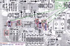
OR: insert a separate 5V voltage regulator for the analog AVDD pins of the DAC. Remove U203 and U202. This trace is no longer used since C901 is removed. Place RD04 in the empty “+” hole of CD07 and in the empty hole of U203 that connects it to U200. Place a new 470uH inductor (+ 2 ferrites) in the other hole of U203 and the hole of U202 that leads to C901. Place a new voltage regulator on the back of the PCB, near C813. Tap power from U267 (-) and U268 (+). Place a small cap at the output of the regulator and connect it with a short wire to the empty “+” pin of C901, that will lead to our new inductor.
Attachments
AndrewT said:Hi,
re post 5232 pic no.2
the caps marked
u 1
100
look like polycarbonate 100V 0.1uF
Since the cessation of polycarbonate film it appears that production has stopped.
What makes a good replacement?
Hi Andrew,
Those are ordinairy polyester caps (MKM). But a good replacement for MKC is MKP, or polystyrene in case of smaller values, or PPS
jimh0612 said:With regard to grounding the coax, I presume the shielding needs to be soldered to the ground plane? I've seen references to the analogue ground plane and the digital ground plane. How critical is it to ensure that the right one is used?
Jim
Hi Jim,
Use the digital ground plane, as all signals are digital, except the HF signal. Mostly the piece of plane that is closest by is somewhere connected to the IC ground, then look in the datasheet which pin it is. The DAC has a separate analog plane at pins 19 and 24.
jksmurf said:Hi Guys,
I was wondering if anyone had a chance to comment on this post #4882 (move so fast this thread, everyone wants a piece of Ray and SimonT and Brent and AVR300 ...
http://www.diyaudio.com/forums/showthread.php?postid=1068860#post1068860
It seems similar, bit not 100% the same to Ray's "OR" in the CD67OSE list.
Hi,
It's about the same, only it uses more regulators to feed the different supply-pins of the DAC. Just tap power from C813, use a L-C filter if you like to supply a new regulator and output cap, and connect it to the DAC. Make sure the supply-pin is isolated first. Some regs need a 1k load to ensure a minimum output current (see datasheet) because some DAC pins draw little current (see datasheet).
Regards,
Ray
It's about the same, only it uses more regulators to feed the different supply-pins of the DAC. Just tap power from C813, use a L-C filter if you like to supply a new regulator and output cap, and connect it to the DAC. Make sure the supply-pin is isolated first. Some regs need a 1k load to ensure a minimum output current (see datasheet) because some DAC pins draw little current (see datasheet).
Thanks Ray, sorry to sound daft again, but do these instructions apply to your "OR" mods or the ones I posted on the jpg above?
k.
- Home
- Source & Line
- Digital Source
- Marantz CD63 & CD67 mods list