Re: Re: Opamp power supply
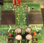
Yes, they are common mode chokes. They were just what I had in stock.
Search ex. Farnell, they have plenty.
imperfectcircle said:
Are those white boxes between the caps the chokes?? What kind are you using?? Im going to be building an outboard supply soon. I plan on building a +-12v and two 5v supplies one each for the analog and digital to power the dac/decoder/clock. Do you know of any good websites about building audio power supplies?? Ive been reading this
tnt audio power supply info
which is for an amplifier power supply, but I would think the info here applies to all audio supplies. Theres also some interesting info on voltage regulators on that website. Any others you guys know about that will help me design my power supply?? I know the basics, but would like to learn as much as possible.
Yes, they are common mode chokes. They were just what I had in stock.
Search ex. Farnell, they have plenty.
Hey what do you guys think about this power supply board from LC Audio? It comes with a transformer and can put out up to +-15v, looks like it would be perfect for the output stage and only cost $60usd. It would be tough for me to build it myself for much less than that. Any opinions???
lc audio psu
lc audio psu
mickie said:Now i'm considering building the output-stage (FET?)...
Ray, what schematic exactly did you use, and: would you build it again, meaning, do you recommend it after all...?
mickie
imperfectcircle said:Im also interested in the discrete ouput stage, can you post the final schematic?? Maybe we can get some PCB's made up??
Hi guys,
The latest output-stage PDF can be found here. The following posts show a few detailed pictures.
Jaap was very kind to draw a PCB for the stage.
If you want to know more you should do a bit of reading around these posts. Or do a search on 'FET'
 .
.Regards,
Ray
Hello folks. Been a lurker on this thread for quite awhile. I am done with about 60% of the mods suggested here and I am quite knocked over by the sound from my 63SE. I have run into a problem however and was hoping for some help. After finishing the gounding work around the servo (U145 and isolate pin 15 to star) I checked to see if all was OK and now the transport won't spin. While checking this I found I had cracked the PCB near the transformer. 1 trace that feeds the 7918 reg. I made a jumper for this but still no go. All voltages seem to be normal to all transistors, regs,IC's except for pin 7 and 8 on Q105 show less than a volt. Also pin 4 on the servo is showing .2V . The 2.5V on pin 7 and 8 is generated internally? This chip is shot? Would appreciate any help.
Imperfectcircle, if you like PM me about Burson products, I am using 1 of there PS, 5 of their "super regs" and also their clock.
Imperfectcircle, if you like PM me about Burson products, I am using 1 of there PS, 5 of their "super regs" and also their clock.
The latest output-stage PDF can be found here. The following posts show a few detailed pictures.
Any possibility we could have some PCB's made up?? Or would anyone make one for me, I would pay for it of course??
Thanks
Frank
compressit said:Hello folks. Been a lurker on this thread for quite awhile. I am done with about 60% of the mods suggested here and I am quite knocked over by the sound from my 63SE. I have run into a problem however and was hoping for some help. After finishing the gounding work around the servo (U145 and isolate pin 15 to star) I checked to see if all was OK and now the transport won't spin. While checking this I found I had cracked the PCB near the transformer. 1 trace that feeds the 7918 reg. I made a jumper for this but still no go. All voltages seem to be normal to all transistors, regs,IC's except for pin 7 and 8 on Q105 show less than a volt. Also pin 4 on the servo is showing .2V . The 2.5V on pin 7 and 8 is generated internally? This chip is shot? Would appreciate any help.
Imperfectcircle, if you like PM me about Burson products, I am using 1 of there PS, 5 of their "super regs" and also their clock.
Hi, and welcome to the thread.
For the groundplane this drawing might come in handy. It's not complete but most grounds are colored blue.
An externally hosted image should be here but it was not working when we last tested it.
The reference voltage is derived from +5V by R124 and R125.
Originally the 5V is coming from the 7805 reg via U163, U166 to R129. The hot side of R129 should be 5V, the other side 2.5V for pin 7 of Q105.
Did you keep U140 and U147?
Check R127, R128 and R136 for faults.
Jaap
imperfectcircle said:Hey Disco, i see that your burning your own pcb's for the output stage. Any possibility that you would be willing to sell me one?? Id love to try the oputput stage but I dont have the equipment for making PCBs.
Thanks
Frank
Sorry Frank,
Making PCBs is not my favourite hobby as it takes two to three hours work. Maybe you can find someone nearby?
Regards, Jaap
disco said:
For the groundplane this drawing might come in handy. It's not complete but most grounds are colored blue.
An externally hosted image should be here but it was not working when we last tested it.
Jaap
What have you used to make this colorcoding? Free hand and MS paint ?

Does the board you designed include the filter section as well as the output ? Do I just connect it to the output of the DAC? Is it a big upgrade over the opamps??disco said:
Sorry Frank,
Making PCBs is not my favourite hobby as it takes two to three hours work. Maybe you can find someone nearby?
Regards, Jaap
thanks
Frank
Re: Re: Re: Re: Re: Re: Re: Opamp power supply
Having a closer look at the specs of these 123 SAL A and SAL AG it seems the dissipation factor is highish (0.12 to 0.18). Other brands have half or even fourth this value. So, high loss.
Strange enough I was not able to find dissipation specs for Black Gate.
Anyone?
Jaap
avr300 said:I think I have a possibility regarding the Vishay. Later! According to LC Audio (a little ago) 123 SAL were chosen as substitute for the BG's. http://www.lcaudio.com/index.php?page=70 - scroll a little down.
Jensen - made in DK
Having a closer look at the specs of these 123 SAL A and SAL AG it seems the dissipation factor is highish (0.12 to 0.18). Other brands have half or even fourth this value. So, high loss.
Strange enough I was not able to find dissipation specs for Black Gate.
Anyone?
Jaap
Yes it does.imperfectcircle said:Does the board you designed include the filter section as well as the output ?
Yes.Do I just connect it to the output of the DAC?
On a scale of 1 to 10 I'd grade the original opamps 4, the FET-out 7 and my tube out 9.Is it a big upgrade over the opamps??
Briefly, there are important upgrades (mostly in the PSU/ decoupling department) and subtle upgrades. The output would be inbetween.
Take care for good PSUs first and than start with finer jobs as outputs, shielding datalines and rewiring ground. The effects of the latter may show after completing the former.
Jaap
avr300 said:What have you used to make this colorcoding? Free hand and MS paint ?
Photoshop and a 23" screen
Strange enough I was not able to find dissipation specs for Black Gate.
...yes, no specs or datasheet available....maybe on demand?
mickie
am new on this forum today am just modding my 63se have disabled the muting circuit i think removed qn05-08 will this do it? or will i have to do more? am now disabling the hdam cicuit have located all resistors except rh23 rh24 can`t seem to find these on my board been looking for hours any help will be most welcome,
Originally posted by rowemeister
Disable muting circuit: remove QN05...08, QN24/25/91/92 and RN27/28 (cuts analog -12V to muting
circuit). Remove U207 and U262 and cut trace there to disable traces running to headphone section.
Decouple each muting line to GND with 2x 100n/X7R at junctions U222/223 and output side to remove
noise coupled-in to analog section from digital-out that runs in parallel with muting lines for several inches!!
the HDAM-circuit looks nice, but when moving up to better opamps and interconnects this circuit starts to
interfere and degrades sound quality. To disable HDAM: remove R651...654 (+/- 12V), R617/618 and
RH23/24. Insert wire jumper at R619/620.
thanks in advance, mik
Briefly, there are important upgrades (mostly in the PSU/ decoupling department) and subtle upgrades
What power supply upgrades are you refering to?? Ive done the basics, schottkys, upgraded caps, chokes+ferites, extra 5v regs for dac/decoder and .1 xr7 smd caps on Dac pins.
Are those the upgrades to the power supply your refering to?? Or are there more i missed?
mikharris said:am new on this forum today am just modding my 63se have disabled the muting circuit i think removed qn05-08 will this do it? or will i have to do more? am now disabling the hdam cicuit have located all resistors except rh23 rh24 can`t seem to find these on my board been looking for hours any help will be most welcome,
thanks in advance, mik
Hi Mik,
Welcome to this thread. I hope you enjoy modding your '63. It's very rewarding and addictive
.The two resistors you mention (RH23/24) are situated under the HDAM shielding-cans. They are the output resistors of this circuit. Hint: if you also remove the output capacitors (C655...685) and U210/214 you can leave them in place and insert a wire between these two points. This way you'll bridge everything with one jumper.
Regards,
Ray.
Attachments
Jaap thanks for your suggestions and diagram. Checked all that you mentioned. U140/U147 are untouched. All voltages to Q105 are fine except pin 7 and 8. The 5v side of R129 is 5V, out put still .2V even after a new 10K. Put this into service mode and the laser started chattering badly, and contiues to do so. Shortly before this I checked voltages at the servo, all 0.0V pins had some voltage, between .2-.4V and pin 17 sadly had 2.5V, supposed to be 0.0V. All 2.5 and 5V pins were spot on.The grounding mod was done correctly, no other pads or traces nearby affected, a minimum of heat was used for attaching the wire at pin 15. All roads seem to be leading back to the servo.I don't think I will like what I am going to hear about this.
6h5c said:
Hi Mik,
Welcome to this thread. I hope you enjoy modding your '63. It's very rewarding and addictive
The two resistors you mention (RH23/24) are situated under the HDAM shielding-cans. They are the output resistors of this circuit. Hint: if you also remove the output capacitors (C655...685) and U210/214 you can leave them in place and insert a wire between these two points. This way you'll bridge everything with one jumper.
Regards,
Ray.
thanks ray, a couple of things,
is that all output capacitors between c655 and c685 or just these two?
also i notice that c651 to 654 are missing do i remove these too?
does that bit of wire run from u210 to r658 and from u214 to r657?
i am very new to this modding lark, first timer!!!!!!!!!!
i have a cd63 which skips a bit when cold only cost me £10 so am going to use this to practice on haha having read in your back posts this is probably cauased by the grease going hard? so might fix that too
have ordered two opamps opa2604(ap) which i am going to run in class A which invloves putting a resistor (3.6k 1/4 Watt carbon film) between pins 1&4 4&7, is this a good thing or will the opamps run to hot? ie will i need heatsinks?
http://home.netcarrier.com/~rstevens/cd67semods.html
also am going to fit schottky diodes,
an iec mains socket (do i have to earth that)?
is it worth me getting the chassis copper plated?
plus all chassis damping i can
not sure how much better it will sound when done
i run it through a rotel rc850 preamp (which i might mod aswell if i can find help on the net)
2x rotel rb970bx mk2 bridged mono running the woofers
2x rotel rb850 bridged mono running the tweeters
ixos interconnects to everything
qed standard biwire
all driving a beloved pair of b&w p4s
the bass is already deep and tight don`t want to loose that if at all possible
thanks, mik
- Home
- Source & Line
- Digital Source
- Marantz CD63 & CD67 mods list