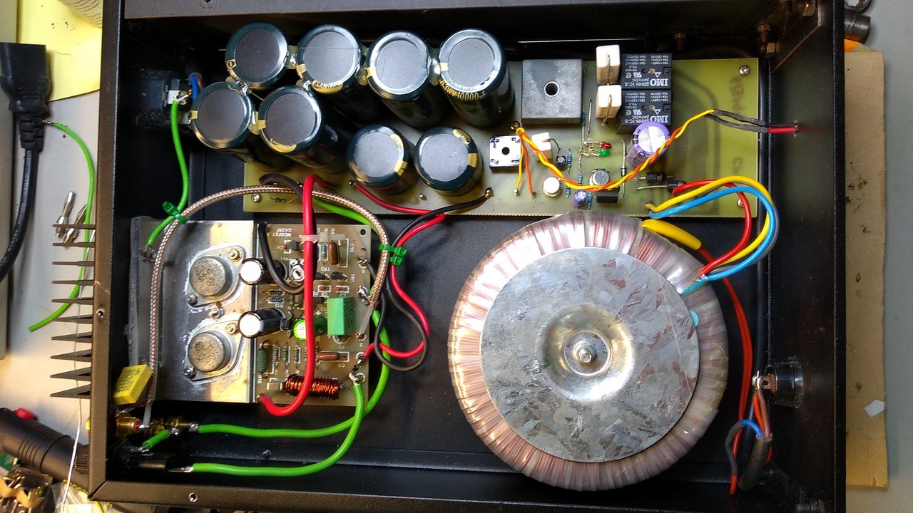
mains earth currently comes in via a 4.7R resistor
mains earth must connect directly to the casing.
read up member bonsai's "how to wire up an amp" presentation.
Yes of course, it's a test case, not very safe ") .
.
The test is because monoblocks (in my case) get plugged into different outlets, so are more prone to earth loops.
The issue is to isolate the case/safety earth from the signal earth, for some reason I'd thought the amplifier heatsink was grounded: but it is isolated. So that makes the solution easy:
.The test is because monoblocks (in my case) get plugged into different outlets, so are more prone to earth loops.
The issue is to isolate the case/safety earth from the signal earth, for some reason I'd thought the amplifier heatsink was grounded: but it is isolated. So that makes the solution easy:
- Modify the input RCA to isolate it's ground from the chassic ground
- Use a shielded cable from RCA in to amp input and star earth.
- Strap the mains earth to chassis as before
- Connect a 120 Ohm res paralled with an X2 0.1uF cap between the star earth and chassis, for EMI purposes, as per Grounding and Shielding for your DIY Audio Projects
Ok, so the new earthing system is complete, and awful
The mains earth is strapped to the metal case, and the signal earth is coupled to that earth via a 120 ohm + 0.1uF X2 cap, paralleled, where it comes in (RCA socket is isolated from the chassis now).
This isolation has been verified and is 120 ohms as intended. Also it does the same on both amplifiers - so this is a design issue: not an error.
The input is fed via a raspberry Pi, which doesn't seem to have an earth.
But it buzzes in the speakers.
Not a hum, a buzz, but the same frequency. It does this with or without the mains earth being plugged in, and with or without being switched on (the capacitors are big, it can run for a while on those).
To eliminate the hum, the mains needs unplugging entirely...
So it's not caused by ripple, and it's not a earth loop..
Perhaps via capacitance from the mains (or fed into the earth wire up the mains cable), is coupling into the signal earth via that 0.1uF capacitor?
But anyway, I'd welcome any answers, as this earth scheme was supposed to be 'great', but does in fact appear to 'suck'.
To summarize:
I can hear a buzz any time the mains power wires are plugged in, regardless of earth connection, or of being switched on or off.
The mains earth is strapped to the metal case, and the signal earth is coupled to that earth via a 120 ohm + 0.1uF X2 cap, paralleled, where it comes in (RCA socket is isolated from the chassis now).
This isolation has been verified and is 120 ohms as intended. Also it does the same on both amplifiers - so this is a design issue: not an error.
The input is fed via a raspberry Pi, which doesn't seem to have an earth.
But it buzzes in the speakers.
Not a hum, a buzz, but the same frequency. It does this with or without the mains earth being plugged in, and with or without being switched on (the capacitors are big, it can run for a while on those).
To eliminate the hum, the mains needs unplugging entirely...
So it's not caused by ripple, and it's not a earth loop..
Perhaps via capacitance from the mains (or fed into the earth wire up the mains cable), is coupling into the signal earth via that 0.1uF capacitor?
But anyway, I'd welcome any answers, as this earth scheme was supposed to be 'great', but does in fact appear to 'suck'
.To summarize:
I can hear a buzz any time the mains power wires are plugged in, regardless of earth connection, or of being switched on or off.
I build and sell Maplin lateral mosfet amps and have never had any problems with hum.
I must admit I did modify it slightly as my original Maplin one hummed a bit.
I added extra decoupling to front end.
Other than that I connect zero volt line direct to earth and have zero hum.
I must admit I did modify it slightly as my original Maplin one hummed a bit.
I added extra decoupling to front end.
Other than that I connect zero volt line direct to earth and have zero hum.
Ok, this issue is only appearing with an Apple USB-C headphone DAC, which usually works fine into my tube and solid state (Leak) amps. Without input, it is silent.
When the Apple DAC is not playnig, it powers down and no hum or buzz is heard.
When asked to play, the buzzing appears when it powers up: even (perhaps more) at low volume.
So my theory is that the DAC is only grounded via the 120 ohm EMI resistor/cap, which allows it some voltage via pickup from the general mains fields: perhaps it needs a more solid earth.
I'll try shorting out the signal ground to mains ground on one of the amps, to see if I need to add a switch for that purpose...
Well, shorting out the 120 ohm resistor had no effect.
Perhaps the loading on the Apple is too high Z, so it's not working properly, it is designed to drive 300 Ohm headphones..
I will try loadng it with perhaps a 1K resistor and see if that helps.
I don't think there's a fault in either item (DAC or Amp), but the combination - not good!
Perhaps the loading on the Apple is too high Z, so it's not working properly, it is designed to drive 300 Ohm headphones..
I will try loadng it with perhaps a 1K resistor and see if that helps.
I don't think there's a fault in either item (DAC or Amp), but the combination - not good!
Try a earth ground breaker.
Tie your earth from the AC line connection thru a 10 ohm resistor to your chassis. Put back to back 30 A diodes across the resistor. You can use a 30A bridge, same as the one you are using in your powers supply. Short the AC terminals on the bridge.
Float the signal in ground from chassis ground.
Good luck
Problem solved !!
It was a noisy USB PSU for the Raspberry Pi - IIRC the one it came with.
I swapped it out for a decent Motorola USB PSU, no more buzzing !!
So the Maplin amps were perfect: just too honest, and showing up a fault with the source...!
It works really well now, although as the Pi+Apple is PSU sensitive, I may try to improve this now!
Thanks for the suggestions ! Moral of story for me: check the source...
Observation..... it is best to connect the safety earth directly to chassis via its own bolt that wont get undone in the process of removing other items. At present if you remove the amp pcb for maintenance/modification you will disconnect the safety earth . Just thinking of your safety .
Thanks, I've moved that now to a dedicated bolt, M4 tapped into the steel chassis.
The mains socket is a clip-in, and there's no guarantee that heatsink is well grounded (due to all the paint, even though it buzzed out), so I wasn't very attached to the old system.
It's a shame health and safety doesn't extend to the medical profession, as hundreds of millions go for an experimental medical device, that generates the same spike proteins that the prestigious 'Salk Institute' assures us are extremely dangerous: we'll see the results of that in the next few years, but already millions are injured and tens of thousands dead (Dr. Bridle, CDC/EMA/UK Yellow card scheme - see Health Impact News etc). Anyway - I don't want to derail the thread.
But I agree with your comment, thanks.
I'm currently playing the Maplins into some EQ'd PA speakers, my 'fun speakers', with 12" eminence drivers, lovely direct sound: huge dynamic range: great fun!!
There's nothing quite like easily moving a lot of air with a large bass unit
A small addition to the story:
I moved these amps to a different room, where I had a switched power supply on a nearby socket: lots of whistling picked up when it was on!
So I soldered a couple of X2 0.22uF caps across the mains input terminals, and that stopped the noise completely
So for the complete solution:
1. Ensure the music source is clean
2. Strap mains earth to any metal case.
3. Use a 120Ohm resistor and 0.1uF X2 cap (parallel) between case and incoming signal ground
4. Use a 0.22uF X1 cap across the mains input to remove any RF.
Incidentally, these are awesome amplifiers
Hello!
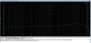
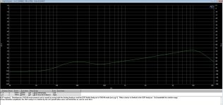
I just powered up one of my Maplin amps via a bench PSU on +/-35V and got the attached THD plots. I haven't shown noise as they are naked, with long, unscreened wires to the PSU.
Notes:
They are using Exicon 20N20 / 20P20 O/P devices.
Plots shown are into a 5R dummy load.
There is a lot of bias. In the 10W test setting, flicking the bias switch from low to high has a massive impact with upper-order harmonics. 3rd seems to really jump down, but the higher-order ones disappear.
They were designed to run 600mA @ +/-75V (or 250mA in the low bias position), so in the plots here @ +/-35V the amp is drawing 500mA (would be 220mA in low position).
Mods:
R3 on the emitters of the LTP has been replaced with a CCS (pair of LEDs and BJTs - was a mod sold by David White AKA White Noise)
R13 Gate R changed to 220R (not sure why R14 is still 100R... Made the amps 22 years ago and memory is fuzzy).
O/Ps have 8V2 zeners back to back with 1N4001 to clamp protect against clumsiness. I wonder if this really will do anything?
Collector Rs for the LTP = 4K7 (not 3K9).
R6 changed to 820R (I plan to make it higher as it has way too much gain for my needs, although I might tweak overall FB R instead)
R9 is 15K not 12K
THD increases with frequency (states obvious). The above mods were done mainly in order to run it at higher rail voltages, so I'm not sure how relevant my quick and dirty test on the 35V bench PSU is...
I have plenty of spares from the days of making Maplin amps and plan to build some DH-200C amps to compare
Attachments
hello
I always use 100 ma bias for 2 Mosfets ...
I get less then 50 mv offset on the output and I use plus / minus 50v DC supply
also I use the original published PSU in the Maplin magazine
hope this helps .. this little amp really packs a punch for its size and price
regards
I always use 100 ma bias for 2 Mosfets ...
I get less then 50 mv offset on the output and I use plus / minus 50v DC supply
also I use the original published PSU in the Maplin magazine
hope this helps .. this little amp really packs a punch for its size and price
regards
Hi all, I've dusted off a couple of original Maplin modules for my little F6B project, and back in an old post there is mention (by Nigel Pearson) of the 47uF feedback arm capacitor.
This is a polarised cap in the diagram, but the suggestion is to change it for a non polarised. Polarising is a situation where when reverse biased, the capacitor acts as a diode - so it's not a linear situation, so the idea is most excellent.
This 47uF cap connects to the base of TR2, which should be around 0V anyway, due to R2 and the mirror. Not sure how accurate a mirror is in DC - perhaps 0, 0.7 or 1.4V, but still at, or close to, 0V (ground).
So my question is: Why bother with the 47uF capacitor at all? Why not just eliminate it? Any thoughts?
Thanks in advance!


@Globulator you can replace that cap with a DC Servo module. In this case you’ll add some more components to the schematic, which is not really what you want to do (considering this type of amp).
What’s good to have is an audio grade cap installed (eg. nichicon muse), parallel with a 1uf MKP film cap.
I hope this helps.
What’s good to have is an audio grade cap installed (eg. nichicon muse), parallel with a 1uf MKP film cap.
I hope this helps.
Thanks guys, I see now, it lets the brakes off the gain at DC so it corrects the DC offset to a fine degree, so either a manual pot somewhere would have to trim it, or a DC servo added.
Good idea to bypass it with a film cap, it needs to be a short, well, at least linear, at audio for the feedback to work well.
Will work out how to fit that in, the destination box is big, but full of 'stuff', so I need to keep things neatly tucked out of the way. The MOSFETs will live on a bigger heatsink so they are off now.
Not sure where these two lived before I inherited them. I did test them, both work and waveforms match, despite the rust.
The previous two I built in the 1980s on my bedroom floor - now in the monoblocks - but these will replace a perfectly good 1977 Sony F6B power amplifier section as I prefer them to bipolars. My F7B wannabe LOL, although that was vFET.
... and it allows me a little DIY tweaking, and to keep these lovely Maplin amps alive and in use.
Maplin and Beatties, the 1980s were heaven
The MOSFETs will have their own independent diode bridge + caps, one per channel, the preamp and this little driver board will be from a 3rd, perhaps via dropper (RC) resistors.
I changed the original 100uF caps for 1000uF but only 50V parts, as these modules were destined for a smaller amp once, but now I have settled on an old 35Vac transformer I had around, which gives about 52V per rail. Power draw for these driver board is about 14mA IIRC, so perhaps 50 ohms into the board and 330uF 63V caps might be ok there - any thoughts?


Good idea to bypass it with a film cap, it needs to be a short, well, at least linear, at audio for the feedback to work well.
Will work out how to fit that in, the destination box is big, but full of 'stuff', so I need to keep things neatly tucked out of the way. The MOSFETs will live on a bigger heatsink so they are off now.
Not sure where these two lived before I inherited them. I did test them, both work and waveforms match, despite the rust
. The previous two I built in the 1980s on my bedroom floor - now in the monoblocks - but these will replace a perfectly good 1977 Sony F6B power amplifier section as I prefer them to bipolars. My F7B wannabe LOL, although that was vFET.
... and it allows me a little DIY tweaking, and to keep these lovely Maplin amps alive and in use.
Maplin and Beatties, the 1980s were heaven
The MOSFETs will have their own independent diode bridge + caps, one per channel, the preamp and this little driver board will be from a 3rd, perhaps via dropper (RC) resistors.
I changed the original 100uF caps for 1000uF but only 50V parts, as these modules were destined for a smaller amp once, but now I have settled on an old 35Vac transformer I had around, which gives about 52V per rail. Power draw for these driver board is about 14mA IIRC, so perhaps 50 ohms into the board and 330uF 63V caps might be ok there - any thoughts?
- Home
- Amplifiers
- Solid State
- Maplin MosFET Amplifier Ga28f construction thread