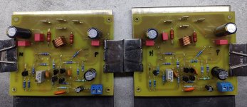
KSC1845, KSA992 ? Though perhaps they'd run a bit hot at 6mA, the 2SD756 and 2SB716's were double-length TO92 packages for extra dissipation. R19 exists to reduce the dissipation in TR3, and it and R3 scale for differing supply voltages.
Its always worth adding zener protection to the gate/source terminals of the MOSFETs, back-to-back 10 or 12V zeners for each device for instance.
Its always worth adding zener protection to the gate/source terminals of the MOSFETs, back-to-back 10 or 12V zeners for each device for instance.
Hellothanks.
and other than the mosfets 2sk150 and 2sj76, what transistors did you use?
i'm thinking different parts than the schematic since those are all long discontinued.
I used 2sk176 & 2sj56 for the power mosfets and the drive signal transistors as per the original design I just posted
Just to note I am the original author of this build thread .. Globulator has modifications and experiments posted here as well
so 2 builds in one thread ... but all from the same start design point
")
Last edited:
Ah yes, apologies about crashing into your thread with my crazy ideasJust to note I am the original author of this build thread .. Globulator has modifications and experiments posted here as well
so 2 builds in one thread ... but all from the same start design point
I think the exuberance around the Maplin amp for me is memories of soldering my first two up, now in monoblock form, on my bedroom floor in the 1980s, probably when they first came out in 1981, on the carpet!
Back then, and still from the perspective of today, Hifi and tech. was rather interesting, a quest for engineering rather than the most expensive cable and youngest corporate 'pop star' LOL
I should probably start a different thread, when I found this one I didn't think I'd be experimenting so much, we can blame Mooly and his LTspice signature for that - haha!
As an indication of the timeless design of these Maplin amps, this thread is nearly 10 years old now!
I'm testing my mods today, on a variator, cheap old car speaker, iPod touch isolated source, via a 10k pot.. so I play some quiet music signal in and see when the sound comes out, which is about 3V per rail, interestingly enough - this design just wants to play music!
So far so good, on minimum bias and 9V, 12V and 20V rails, all is good, scope confirms all is clean, so this afternoon I'll try the other board, and then see if I can set the bias Ok and everything still looks good.
Thanks James, you are a star!
I tested the modified Maplin boards yesterday and today, will continue for the next few days.
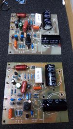
All is built as shown except R1 is a 2k as i didn't have a 1.8k.
It starts playing music at only 1.8V per rail, which is interesting, cleanly at about 3V.
Testing at 22V rails on a small transformer (15-0-15) well into clipping at times revealed very clean clips, surprisingly loud too, at that low voltage
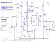
The original 6n8 capacitor is I think to drive the Wilson mirror slightly 'sharper' at high frequencies, but it has the effect of a nasty +ve clip (It goes concave, some effect of the base of TR5 being pulled about), so eliminating that, adding the bleed 270k and rebalancing makes it clip very cleanly and recover very fast. It's not soft clipping, but it is very elegant.
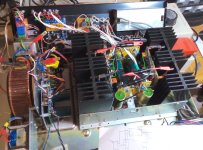
Today I planted it into it's home and wired it up to to the 51V rails, biased up to 80mA, and again it behaves flawlessly. Very quiet, too. The CCS on the input helps PSRR etc I think, having the rails bouncing about with the music going to TR1 and TR2 was something I aimed to eliminate.
LTspice says the distortion levels are low enough to make grown men weep, I'll need some more listening time to see what I think too. So far so good, I'm rather pleased with the changes, as they appear to actually work, so I'll see how well listening ties up with LTspice.
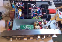
My Hitachi's are driven direct from the supply (via 2AT fuses), the driver board is via two schottky diodes and 39R (IIRC) resistors into 1000uF caps, so that's well smoothed and immune(ish) from PSU rail sags.
I also worked out that these boards are up to 43 years old, and my original 2 I probably did build in 1981. If I had a time machine I'd go back
I tested the modified Maplin boards yesterday and today, will continue for the next few days.
All is built as shown except R1 is a 2k as i didn't have a 1.8k.
It starts playing music at only 1.8V per rail, which is interesting, cleanly at about 3V.
Testing at 22V rails on a small transformer (15-0-15) well into clipping at times revealed very clean clips, surprisingly loud too, at that low voltage
The original 6n8 capacitor is I think to drive the Wilson mirror slightly 'sharper' at high frequencies, but it has the effect of a nasty +ve clip (It goes concave, some effect of the base of TR5 being pulled about), so eliminating that, adding the bleed 270k and rebalancing makes it clip very cleanly and recover very fast. It's not soft clipping, but it is very elegant.
Today I planted it into it's home and wired it up to to the 51V rails, biased up to 80mA, and again it behaves flawlessly. Very quiet, too. The CCS on the input helps PSRR etc I think, having the rails bouncing about with the music going to TR1 and TR2 was something I aimed to eliminate.
LTspice says the distortion levels are low enough to make grown men weep, I'll need some more listening time to see what I think too. So far so good, I'm rather pleased with the changes, as they appear to actually work, so I'll see how well listening ties up with LTspice.
My Hitachi's are driven direct from the supply (via 2AT fuses), the driver board is via two schottky diodes and 39R (IIRC) resistors into 1000uF caps, so that's well smoothed and immune(ish) from PSU rail sags.
I also worked out that these boards are up to 43 years old, and my original 2 I probably did build in 1981. If I had a time machine I'd go back
Attachments
I found a similar thread here, about the Maplin amplifier:
https://www.diyaudio.com/community/threads/vas-requirements-for-mosfet-ops.404529/
As the original theme, as i saw it, when I was young, of Maplins, was to get people interested in learning about electronics - 43 years on it was a spectacular success, as people are still learning today - especially me
Maplins and Beatties in the 1980s, and the HiFi shops, model shops - a fantastic era in England.
Listening tests continue, plus minor hardware tidy ups, I haven't got a very clean square wave source, to check for ringing but the music waveforms are very clean - no fuzz, but that's the last thing I need to confirm, but all temperatures are good and I jacked it up to 105mA (23mV over a 0.22R test resistor slotted in) bias - due to the graph at the bottom of this page:
https://www.edgrochowski.com/articles4/classab.html
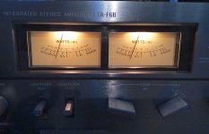
The original host amp box here that the heatsinks were made for was 100WPC, this realistically has 120WPC max music (45V clip), average loud music here (quite efficient speakers) sits at about 1 Watt so it didn't break a sweat, perhaps reaching 20W continous on Tubular Bells - the bass guitar bits.
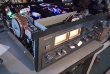
I've probably modded these original Maplin boards as much as I need to, I'll write up some of the Sony stuff in a different thread as that's off topic here - many thanks for James for starting this long running thread, a font of information, and keeping these sweet little boards in my view!
Useful implementation mods I found:
1. Seperate the supplies to the MOSFETs and the driver. My diode idea worked better than I'd hoped, it stops the driver caps draining into the power MOSFETs, keeps the driver section much happier.
2. Mounting the toroid on it's side - as James also has, solves a lot of space issues!!
3. Using old vintage amplifier boxes - Ok it's sort of sacrilege in a way - but has big benefits.
4. One day I should budget for new PCBs to my spec, to integrate all ideas, options and PSU !!
5. I added quite a few fuses, unusal for me, I must be getting old LOL.
6. eBay soft start relay with 56R resistor (240V mains) works like a charm.
Useful design mods I found:
1. Douglas Self's words of wisdom: http://douglas-self.com/ampins/dipa/dipa.htm
2. CCS on the input (run at 3.5mA thanks to Douglas, - it then drives TR3/4 much better)
3. Eliminating the 6n8 - now it clips cleanly.
4. Bigger transistors - like James uses, perhaps for me the 2SA1145 / 2SC2705 pair, for more VAS bias - later..
5. Balancing the circuit for lowest distortion, simply allowing the LTPs to function a little better, I suspect this upped the open loop gain.
6. 33k input resistor on TR1 - to reduce offset.
Lessons for me:
1. LTspice is really useful - thanks Mooly!
2. Class A really does have way less distortion - how the driver deals with crossover distortion appears to be key to the sound, and mainly affects the most populat listening levels of 0.5 - 3W, so this region is super critical.
3. Still many things about design remain to be learned!
4. This amp starts working at +/- 3V rails, which surprised me!
And the main thing about DIY, the sound blows the socks off commercial offerings, while also allowing us to listen through something we actually built - priceless!.
These boards are awesome!
https://www.diyaudio.com/community/threads/vas-requirements-for-mosfet-ops.404529/
As the original theme, as i saw it, when I was young, of Maplins, was to get people interested in learning about electronics - 43 years on it was a spectacular success, as people are still learning today - especially me
Maplins and Beatties in the 1980s, and the HiFi shops, model shops - a fantastic era in England.
Listening tests continue, plus minor hardware tidy ups, I haven't got a very clean square wave source, to check for ringing but the music waveforms are very clean - no fuzz, but that's the last thing I need to confirm, but all temperatures are good and I jacked it up to 105mA (23mV over a 0.22R test resistor slotted in) bias - due to the graph at the bottom of this page:
https://www.edgrochowski.com/articles4/classab.html
The original host amp box here that the heatsinks were made for was 100WPC, this realistically has 120WPC max music (45V clip), average loud music here (quite efficient speakers) sits at about 1 Watt so it didn't break a sweat, perhaps reaching 20W continous on Tubular Bells - the bass guitar bits.
I've probably modded these original Maplin boards as much as I need to, I'll write up some of the Sony stuff in a different thread as that's off topic here - many thanks for James for starting this long running thread, a font of information, and keeping these sweet little boards in my view!
Useful implementation mods I found:
1. Seperate the supplies to the MOSFETs and the driver. My diode idea worked better than I'd hoped, it stops the driver caps draining into the power MOSFETs, keeps the driver section much happier.
2. Mounting the toroid on it's side - as James also has, solves a lot of space issues!!
3. Using old vintage amplifier boxes - Ok it's sort of sacrilege in a way - but has big benefits.
4. One day I should budget for new PCBs to my spec, to integrate all ideas, options and PSU !!
5. I added quite a few fuses, unusal for me, I must be getting old LOL.
6. eBay soft start relay with 56R resistor (240V mains) works like a charm.
Useful design mods I found:
1. Douglas Self's words of wisdom: http://douglas-self.com/ampins/dipa/dipa.htm
2. CCS on the input (run at 3.5mA thanks to Douglas, - it then drives TR3/4 much better)
3. Eliminating the 6n8 - now it clips cleanly.
4. Bigger transistors - like James uses, perhaps for me the 2SA1145 / 2SC2705 pair, for more VAS bias - later..
5. Balancing the circuit for lowest distortion, simply allowing the LTPs to function a little better, I suspect this upped the open loop gain.
6. 33k input resistor on TR1 - to reduce offset.
Lessons for me:
1. LTspice is really useful - thanks Mooly!
2. Class A really does have way less distortion - how the driver deals with crossover distortion appears to be key to the sound, and mainly affects the most populat listening levels of 0.5 - 3W, so this region is super critical.
3. Still many things about design remain to be learned!
4. This amp starts working at +/- 3V rails, which surprised me!
And the main thing about DIY, the sound blows the socks off commercial offerings, while also allowing us to listen through something we actually built - priceless!
. These boards are awesome!
Attachments
Hi all!
Just an update on some listening tests, with the Maplin board built with the C1 input capacitor at 10uF, and the feedback capacitor C3 at 220uF, which on paper gives tremendously good bass performance.
So testing this with an MC20 playing a quite flat, well pressed Decca vinyl copy of Strauss's 'Also Sprach Zarathustra' - the great intro to 2001, a Space Odyssey - through an MC20 + head amp + phono of the Sony F6B preamp ..
... revealed a prodigious amount of infra-sound bass. So much, in fact, that at one time the amplifier really started to lose control of the DC and the woofer was very slow, 1second-ish, at returning to the correct position.. so much so that the speaker protection relays only gave me the edited highlights
I switched in the 15Hz HPF on the Sony and everything was much better.
So after a few simulations, I've therefore concluded that C1 at 0.68uF and C3 at 33uF, will provide way enough bass, dropping only 0.25dB at 32Hz, 0.5dB at 20Hz and down at -30dB at 1Hz - is a better bet.
So the original values of 1uF and 47uF do seem to be better than my ideas of 10uF and 220uF/470uF etc, and now I'm thinking that to really keep things tidy, 0.68 and 33uF might be best.
If anyone else has some insight into this, please say!
I used the Maplin amps for subwoofers.
Low frequency noise is expected with a vinyl record due to warps and such, but I experienced extreme low frequency problems on CD, in a recording made in a church, where low frequency wind noise caused difficulties for my subs.
Whatever the choice of components in the amp, a high-pass filter is a very good idea, where a steeper slope can be used.
- Home
- Amplifiers
- Solid State
- Maplin MosFET Amplifier Ga28f construction thread