Hi Guys
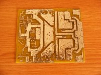
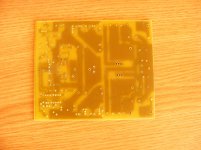
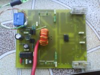
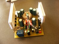
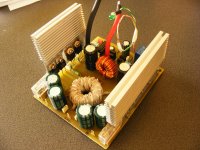
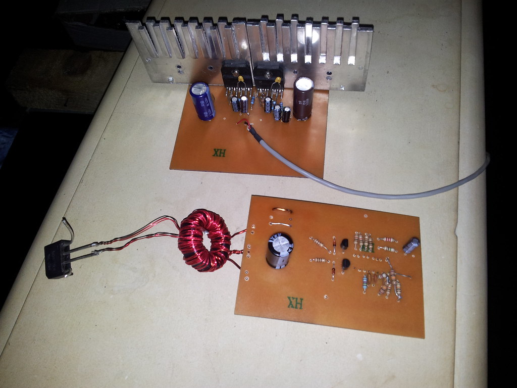
I have made an amp + smps for my Contessa Classic car.
The smps uses
SG3525 PWM IC
12 X IRFZ44N mosfets
12 X 47ohm Gate resistors
1 X E-I CRGO 4 No. Iron Core Transformerrimary=12-0-12 Multifillar Winding and Secondary 50-0-50 Windings.
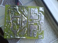
one Vero board
2 X 100mFd 25V Caps
2 X 0.1mfd 50V ceramics cap
Couple of other resistors and caps etc.
Frequency is 250Hz
No - Feedback is applied , therefore efficiency is high.
1 X 3.5mFd/250V cap is directly connected to secondary of transformer to suppress spikes.
2 X small heat sinks.
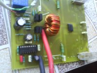
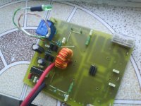
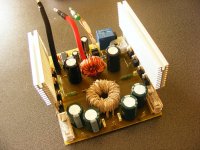
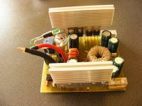
Now the results
No heating on full load only simple warming of sinks
650W power capability
Still alives and is breathing in my car
IF any one interseted mail me.
I am interseted please send to me
thanks very much
wavetech_lab@hotmail.com
Hi to all, i want to build a smps from Rod Elliott's project 89 using 8Riccardo9's pcb and i have a white toroid of 3F3 material, 3.2 cm diameter (i attached the datasheet). I want to ask you guys:
1. how many turns should i wind for the primary and what thickness?
2. at what frequency i would sqeeze the maximum power out of this toroid?
3. and how much power would i obtain using this toroid?
I will be using this smps for my upcoming car-amplifier, i haven't decided yet what kind of amplifier i will use but i don't want to have more than +/- 30V from the smps because i could't find lowESR caps for the smps with more than 35V (would regular caps work well?), all other components are the same with the ones in the pcb.
Attachments
Last edited:
4 turns or 5, and depends on your power need, how much wire.. I would do 3x 1mm for each primary, 2x 1mm for each secondary, or something like it
2. The the higher the more power you can transfer, so probably over 300kHz... which YOU won't use
3. don't know, depends on what you do with it, can be from as little as say 50w, to probably over 1kw with some crazy high freq.
Non low esr caps will work just fine, even better if your swithching freq. is below 40k.
Hello again, today i mounted on the pcb the sg3525 and adiacent components + bd139/140 drivers and i want to ask you if there is a problem on the SG inputs/outputs:
pin 9 - 5.6V
pin 11 - 4.99V - rises in about two seconds to about 5 volts
pin 14 - 4.97V - rises in about two seconds to about 5 volts
pin 16 - 5.09V
pin 1 - 5.09V
pin 2 - 5.09V
Is this ok?
On pin 11 & 14 i should have about 12V right?
Here are some pics (sorry about the quality)
pin 9 - 5.6V
pin 11 - 4.99V - rises in about two seconds to about 5 volts
pin 14 - 4.97V - rises in about two seconds to about 5 volts
pin 16 - 5.09V
pin 1 - 5.09V
pin 2 - 5.09V
Is this ok?
On pin 11 & 14 i should have about 12V right?
Here are some pics (sorry about the quality)
Attachments
Please for the PCB layout for this schematic.himanshuraval,
Just a question, are you using a heatsink for the mosfets?
I am using the following circuit and it work perfectly. I am still working with two types of cores (toroid and ETD39)...for now the toroid is performing better and much easier to wind..
An externally hosted image should be here but it was not working when we last tested it.
If you are able to more data for ferrite transformer ETD39, .. how much the primary winding to the secondary ? Wire gauge for primary and for secondary section ?
thanks
Last edited:
ASK
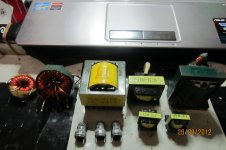
I have several models I use a transformer to make a SMPS. but I had never before made the SMPS and transformer which I can use to build it. Can my friends help me to build an SMPS transformer specifications that I have. I hope you all do not mind to help me. I plan to make a car amplifier with an input supply ACCU 13.8 V.
regards
The following picture.
Attachments
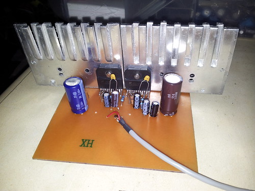
Hi. Here is my SMPS using the TL494. I am going to use it with two LM3886 amp chips.
I am waiting for some diodes for the bridge. I ordered these FR602 100V 6A Fast Recovery Diode. I hope they are OK because I could not find better once.
I am waiting for some diodes for the bridge. I ordered these FR602 100V 6A Fast Recovery Diode. I hope they are OK because I could not find better once.
An externally hosted image should be here but it was not working when we last tested it.
An externally hosted image should be here but it was not working when we last tested it.
An externally hosted image should be here but it was not working when we last tested it.
Project89 ESP Mod
How do I apply an optoisolator (such as 4N25, sfh610, CNY17) to make the feedback on sg3525 to adjust the output voltage? My Transformer it’s adequate to make this project?
I’ve winded 4sp + 4sp on the primary, 12sp + 12sp on the secondary (1:3)
My transformer have an 3C80 (15G) material and it’s an E 42 21 15 type.
- Status
- This old topic is closed. If you want to reopen this topic, contact a moderator using the "Report Post" button.
- Home
- General Interest
- Car Audio
- Making car amplifier SMPS with tl494 + DC Protection