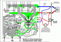
Double sided PCB
Hi there,
Double sided PCB making requires precision. You must have a PCB properly laid out based on its schematics. Laying out the tracks would be relatively easy as long as you have reliable software to use. Parts placements also plays a critical in making the circuit reliable. In terms of current handling for the tracks made on the board.
If you have the PCB layout sample, please post it.
Regards,
Blueice23
Hello,
Guys I am going to etch a smps board , It is double sided.
I a double sided board w, i dont know how and where the top layer connects with the bottom layer. Please guide.
Hi there,
Double sided PCB making requires precision. You must have a PCB properly laid out based on its schematics. Laying out the tracks would be relatively easy as long as you have reliable software to use. Parts placements also plays a critical in making the circuit reliable. In terms of current handling for the tracks made on the board.
If you have the PCB layout sample, please post it.
Regards,
Blueice23
and you would be wrong here, since even sine does not consume that much power, let alone music... with this you would only need peak power of say 500w, not constant... which means you can make a lot smaller supply... and even more, if you have more output capacitance, you have there stored a lot od energy, that does not need to be transfered from primary side, since it is already stored in output capacitors
then again
make 2 supplys, one for low powew amps, and one for higher
coz you don't need +/-55v on class AB amp to waste most in heat for 120w of output
then again
make 2 supplys, one for low powew amps, and one for higher
coz you don't need +/-55v on class AB amp to waste most in heat for 120w of output
I am making Ax-14 By apex for stereo.
For Mono Amp i haven't yet finalized, I am having hv350 by apex in mind. Do you have any good Pcb layout of sub amp with output of 250 watts @4ohms.
Also layout of Smps for these amps.
I am trying to make all these made on a single pcb.
Hoping for the best, lets see.
Ty
For Mono Amp i haven't yet finalized, I am having hv350 by apex in mind. Do you have any good Pcb layout of sub amp with output of 250 watts @4ohms.
Also layout of Smps for these amps.
I am trying to make all these made on a single pcb.
Hoping for the best, lets see.
Ty
no, I have a bit stronger amps just for front stage, subs get a bit more power than that 
My supply for 4ch amp
My supply for 4ch amp
well... yes, if you don't have too big alt, that would charge in 15v range...
its also good to first know that your trafo is made good, while spikes from swithching are not a problem for fet, you should still make sure before you install it for ever
also, unregulated might be better, since its always full duty, but can't say for sure
I would say you are cutting it close, more then needed, coz unless you already have the fets, I would look for atleast 40v ones
Which components will a have to change, to reach more AMPs? I would use IRFZ44N mosfets, core for transformer (similar sizes to ETD39) from ATX psu, bigger bridge and bigger capacitors. On the high AMP PCB traces I would sold extra copper wire. Anything else?
Greetings from Slovenia!
Robert Vitez
Greetings from Slovenia!
Robert Vitez
components are not really a problem to some point, since you are going with relatively small core, core is the first to be maxed out (at some freq.)
single 44n per side of the push pull would be good for at least 400w.
also depends on what you want to make it for.
single 44n per side of the push pull would be good for at least 400w.
also depends on what you want to make it for.
Last edited:
- Status
- This old topic is closed. If you want to reopen this topic, contact a moderator using the "Report Post" button.
- Home
- General Interest
- Car Audio
- Making car amplifier SMPS with tl494 + DC Protection
