djolejr said:.....If anyone need books about smps i can upload it on Rapidshare:
1. (Elect Pwrelect Smps) - 0-07010-951-6 High Frequency Switching Power Supplies Theory And Design - G Chryssis.pdf 36MB
2. (Elect Pwrelect Smps) - Keith Billings-Switchmode Power Supply Handbook 1St Ed - Book.pdf 36MB
3. BROWN, M. (1990). Practical Switching Power Supply Design pdf 10MB
4. BROWN, M. (2001). Power Supply Cookbook (2nd ed.) pdf 3MB.....
[/url]
Yes, I'm interested, especially in both the Brown Publications and Chryssis..
Steve
I have noticed that when i turn off switch (new schematic) one of fets for a very short time is turned on, and because of that current for that short period of time become very large (this forced transformer to make noice during shutdown,so i noticed this). This is happened probably because Voltage is not suficient for TL494 and one of transistors in it continues to conduct but Voltage is sufficient for CD4050 thus this, one of fets stay turned on.
I added circuitry that prevent CD4050 to work when Voltage is below 9V.
I added circuitry that prevent CD4050 to work when Voltage is below 9V.
Attachments
What is the purpose of CD4050 ?
You can obtain 150W, and more ( @38KHz ) from single EI33 core.
It's better to isolate input and output ground.
TL494 also need power supply ( pins 7 and 12 ) - drawing error ?
I need those books so, please, upload them on Rapidshare.
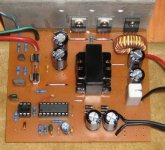
This is the pic of my DC-DC ( max 120W, core EI28@55KHz ) for small class D amp.
You can obtain 150W, and more ( @38KHz ) from single EI33 core.
It's better to isolate input and output ground.
TL494 also need power supply ( pins 7 and 12 ) - drawing error ?
I need those books so, please, upload them on Rapidshare.
This is the pic of my DC-DC ( max 120W, core EI28@55KHz ) for small class D amp.
Attachments
m-tech said:What is the purpose of CD4050 ?
You can obtain 150W, and more ( @38KHz ) from single EI33 core.
It's better to isolate input and output ground.
TL494 also need power supply ( pins 7 and 12 ) - drawing error ?
I need those books so, please, upload them on Rapidshare.
This is the pic of my DC-DC ( max 120W, core EI28@55KHz ) for small class D amp.
Hi M-Tech,
Very nice proto, Please put here schematic and pcb file
by using CD4050 transition from 0V to Vcc or Vcc to 0V is much faster (t rise or t fall are very small), because input capacitance of CD4050 is much smaller than discrete transistors and output pair of transistors in IC are very fast and with low Vds so you may potentionaly spare some power.
I have used Protel99 to drew scheme, and in protel there are not pins for supply at symbols for many of ICs.
I have used Protel99 to drew scheme, and in protel there are not pins for supply at symbols for many of ICs.
Transformer Heating up
I have made this circuit for 28v single rail output and getting 7amps.
I am facing a problem with the toroid...its get hot after using it for only few minutes...
there is no problem in voltages or amps...i am getting the right amount of it. but, heating is an issue...
all the rest of the parts are in normal temperature...even the mosfets are fine.
i am using a single high speed diode on a single winding out from the transformer.
is there anything i am missing?
if i use ETD39 core at the place of toroid, is it gona fix this problem?....
If any1 can guide me to fix this issue...i will be really greatful...
Thanks.
Re: Transformer Heating up
In a push-pull converter symmetric output rectification is required for proper core flux balancing. Use either two windings in opposite directions and two diodes or a single winding with four diodes.
aliazhar said:I have made this circuit for 28v single rail output and getting 7amps.
I am facing a problem with the toroid...its get hot after using it for only few minutes...
there is no problem in voltages or amps...i am getting the right amount of it. but, heating is an issue...
all the rest of the parts are in normal temperature...even the mosfets are fine.
i am using a single high speed diode on a single winding out from the transformer.
is there anything i am missing?
if i use ETD39 core at the place of toroid, is it gona fix this problem?....
If any1 can guide me to fix this issue...i will be really greatful...
Thanks.
In a push-pull converter symmetric output rectification is required for proper core flux balancing. Use either two windings in opposite directions and two diodes or a single winding with four diodes.
i have tested this circuit again with single winding 4 diodes....same result....
transformer still gets hot...if i leave it for a very little bit, it smokes....
my transformer data:
Ferrite Toroid core size OD=1.8"
Primary: 22-AWG (two wires together) = 12+0+12
Secondary: 22-AWG (two wires together) = 24 turns (single winding)
any more suggestions?
transformer still gets hot...if i leave it for a very little bit, it smokes....
my transformer data:
Ferrite Toroid core size OD=1.8"
Primary: 22-AWG (two wires together) = 12+0+12
Secondary: 22-AWG (two wires together) = 24 turns (single winding)
any more suggestions?
What material is the core made of?
Operating frequency?
Is the core actually getting hot or is it only the wire that's overheating?
Two 22g wires will not be enough for the primary. You'll need two 14g or the equivalent. You may need something larger (more copper) if this is designed for 100% duty cycle operation.
You should try a center tapped secondary (9+9 or 10+10).
4+4 on the primary should work well at ~30kHz.
Thanks for your reply.
i dont know about the exact frequency of the core....but, it is made for high frequency....i took this core out of NEC Plasma powersupply...
the core itself does'nt get hot, its the copper wire which gets hot...
i have already ordered ETD39 and another core from surplussales.com and am going to try them once i receive them in couple of days.
I am also gona try your calculated gauge and turns on it and will post the results...
hi !
how can i calculate sg3525 ics frequency ?
i didnt see a clear formula in datasheets !
excuse me if i ask silly questions because i am not a EE !
i am an IE !!
i have a avo meter with frequency measurment capability ,
when i use both two probes to measure frequency shows 7 khz
but when i use a single probe it shows 37khz !
witch method is correct ??
best regards
Frequency (bottom of page 4):
http://www.st.com/stonline/products/literature/ds/4286/sg3525.pdf
Black lead on ground and red lead on the gate of the transistor or red lead on the output of the IC (pin 11 or 14) will probably produce the most accurate readings.
http://www.st.com/stonline/products/literature/ds/4286/sg3525.pdf
Black lead on ground and red lead on the gate of the transistor or red lead on the output of the IC (pin 11 or 14) will probably produce the most accurate readings.
thank you perry
i used to check farchild , sg and samsung 3525 ics datasheet but they didnt put the formula on their datasheets (maybe "datashit"
but ST did it !
below picture is the schematic of my smps.
can you help me to calculate the frequency ?
i already made and used it , but i think performance is lower than expected.
i used discharge resistance as Rd =100 ohm and other values , formula says frequency should be around 136 KHz but avo meter says 7.5KHz (according to your wrotes about avo meter leads)
so what do you think ?
hint : my winding is 4+4 for primary , and i think 40KHz is suitable frequency.
i used to check farchild , sg and samsung 3525 ics datasheet but they didnt put the formula on their datasheets
(maybe "datashit" but ST did it !
below picture is the schematic of my smps.
can you help me to calculate the frequency ?
i already made and used it , but i think performance is lower than expected.
i used discharge resistance as Rd =100 ohm and other values , formula says frequency should be around 136 KHz but avo meter says 7.5KHz (according to your wrotes about avo meter leads)
so what do you think ?
hint : my winding is 4+4 for primary , and i think 40KHz is suitable frequency.
Attachments
- Status
- This old topic is closed. If you want to reopen this topic, contact a moderator using the "Report Post" button.
- Home
- General Interest
- Car Audio
- Making car amplifier SMPS with tl494 + DC Protection