ok....did some more experiments....and found few reasons of the faults i was getting.
the first one:
copper wire on toroid was getting hot: reason, copper wire was bought from radioshack...and was tooo low quality.
ETD49 core:
no luck on getting what i wanted to get out of them....so, i am back on Toroids.
made the circuit again, since it was soldered too many times.....still using IRF540's...which i will change to IRFZ44's early next week.
using toroid, output voltages after winding was arround 40v....i have put a 12x2 volts halogen bulb...and the volts drops to 12 !!!
few question after all these experiments if you can help:
1. is it possible to adjust output volts with some kind of variable....to keep them constant at 42volts ?....with or without load
2. what is the best size/made toroid to use for this?
3. at 42v/15amps, how many IRFZ44's are needed to run them on a normal heatsink with or without fan?
I will be in a much better shape in my project after getting these answer...
please help if you can.
Thanks for all of you guyz !
1. You'll need to use regulation to keep it constant.
2. I'm sure others have their preferences but I'd recommend a ZP-44916-TC from magnetics (mag-inc.com). If that's not available, use a ZF-44916-TC.
3. Use 12 total Z44s. For continuous (100% duty cycle), I'd recommend 6 strands of 14g for the primary. Use 4+4 primary turns and 16+16 secondary turns. That will give you ~±48v. The regulator will bring it down. To maintain 42v, you may have to go with a slightly higher ratio but you want to use the lowest ratio possible to minimize current draw.
You will need to use a large number of low impedance, high temp capacitors on the primary. You'll have to experiment to see how many you'll need when you connect your device to it. I'd start with 10-12 330uf@35v caps on the primary side.
You can expect this power supply to draw at least 80 amps continuous from the 12v supply.
Hopefully some of the power supply gurus will post their suggestions.
Perry Babin said:1. You'll need to use regulation to keep it constant.
2. I'm sure others have their preferences but I'd recommend a ZP-44916-TC from magnetics (mag-inc.com). If that's not available, use a ZF-44916-TC.
3. Use 12 total Z44s. For continuous (100% duty cycle), I'd recommend 6 strands of 14g for the primary. Use 4+4 primary turns and 16+16 secondary turns. That will give you ~±48v. The regulator will bring it down. To maintain 42v, you may have to go with a slightly higher ratio but you want to use the lowest ratio possible to minimize current draw.
You will need to use a large number of low impedance, high temp capacitors on the primary. You'll have to experiment to see how many you'll need when you connect your device to it. I'd start with 10-12 330uf@35v caps on the primary side.
You can expect this power supply to draw at least 80 amps continuous from the 12v supply.
Hopefully some of the power supply gurus will post their suggestions.
this is really great info and excellent help...
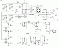
now, th regulation: i dont know how to implement that with sg3525....can i get any schematic/link on that?
Thanks again!
I don't use the SG ICs and they work a bit differently than the 494/594 but this is essentially what you'll need to do.
You'll use the internal comparator. Create a voltage divider with 2 equal value resistors. The top of the divider will be connected to the regulated 5.1v of the 3525. The bottom of the divider will be grounded. The point where the resistors connect will go to the non-inverting input of the comparator.
You will use another voltage divider to feed back the rail voltage to the inverting input of the comparator. One of the outer terminals of the pot will be connected to the rail voltage. The other outer terminal will be conected to ground. The wiper will go to the inverting input of the comparator. You'll set the pot to control the regulated voltage. You can make the adjustment a bit easier by adding a resistor between the rail voltage and the pot.
You'll have to select a pot with enough resistance so that the voltage across it will not produce power dissipation greater than its power rating.
Page 6, figure 8 has a similar circuit. It's a different IC but they function the same.
http://bcae1.com/temp/sg3524.pdf
Hi
You didn't read this thread, or any other, did you?
On first page you have schema of smps that has feedback/regulation. Thats one way of doing it...the other way, you can find where I posted my supply, it is not 12V supply but if doesn't matter...if you will search for it and find it, just look how opto is connected, not what is on secondary side....just how is connected to SG. And there is another way... but there you don't have insulation between primary and secondary...your choise
luka said:Hi
You didn't read this thread, or any other, did you?
On first page you have schema of smps that has feedback/regulation. Thats one way of doing it...the other way, you can find where I posted my supply, it is not 12V supply but if doesn't matter...if you will search for it and find it, just look how opto is connected, not what is on secondary side....just how is connected to SG. And there is another way... but there you don't have insulation between primary and secondary...your choise
you are right...i have'nt read it all....i should have...
i have made a simplest circuit using the pcb from this thread....which works on 37khz....
i am building this circuit again with the PCB and 100% according to the schematic...
now, the feedback in this circuit is taken from +/-30...
dont you think it need to be adjusted since i want to use it on 42v single supply ?....
what do i need to change in the feedback circuit to achieve that or can i used the same as is?
Thanks again for your help guyz !
Hi
If you are going to do FB with zeners, just change zeners so, that they will add to what you want. Original was +/-30=60v so 2x 30v zeners, in your case you will have to put some other, zeners don't have to be the same...
If you will use same board as in this thread you need to change only zeners to set output
Ps: but when you get to transformer winding, say so here, I don't want you to just wind it as easy as you could...you should do it the right way
I have tried this with zener..... I have used two 22v zener in series....
the result is:
whenever i turn it on, it keep increasing the output voltages....
i have put the voltmeter...
it does'nt stop at 44v ...
why its happening this way?...it should stop at 44v !
is there any other way to use feedback on sg3525 ?
Thanks !
the result is:
whenever i turn it on, it keep increasing the output voltages....
i have put the voltmeter...
it does'nt stop at 44v ...
why its happening this way?...it should stop at 44v !
is there any other way to use feedback on sg3525 ?
Thanks !
you are right....
well...it was my mistake....now, both of them works like a charm...
i am now, using the optical version....which works like a charm....
voltages fixed at 44v..... frequency is being auto-adjusted !!!
this is getting really very interesting....
now, some test results...
i have used the original pcb with 4 mosfets...:
got arround 4 amps out...
then i have moved a bit furthur...
i am using 5 mosfets on each side
with BYV72 rectifiers.....in a brigde.
results till now:
44v at 9 amps.....i have'nt tested it furthur...since i had to leave my battery for charging...
on the transofrmer: (at the moment)
Core: ETD49
Primary: 0.4mm (26-awg) 16x 4 turns
Secondary: 0.4mm (26-awg) 8x 12 turns
I will post more results once i figure out the transformer ratio.....
i will also post pictures by tommorow morning.
Thanks again !
Perry Babin said:3. Use 12 total Z44s. For continuous (100% duty cycle), I'd recommend 6 strands of 14g for the primary. Use 4+4 primary turns and 16+16 secondary turns. That will give you ~±48v. The regulator will bring it down. To maintain 42v, you may have to go with a slightly higher ratio but you want to use the lowest ratio possible to minimize current draw.
6 strands or 14-awg wires for primary...
and how many6 strands of 14-awg for secondary?
also 6?
luka said:Hi
6 strands OF 14-awg wires for primary, 2 or 3 for secondary... I want to see pictures, lol never seen ETD49 in 12v smps
i have used 24 strands of 26-awg for primary
and 12 strands of 26-awg for secondary....
still testing...results are satisfactory...will post some results soon.
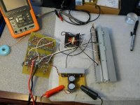
till then, here is a picture.
Attachments
You're going to have to minimize the resistance between components to get significant power out of the supply. The thin wires between the various components are going to induce significant loss in the circuit.
What load are you using to test the circuit?
Are you connecting the load from the center tap to the positive output or are you connecting it from the positive output to the negative output?
How low is the voltage dropping across B+ and ground?
What load are you using to test the circuit?
Are you connecting the load from the center tap to the positive output or are you connecting it from the positive output to the negative output?
How low is the voltage dropping across B+ and ground?
- Status
- This old topic is closed. If you want to reopen this topic, contact a moderator using the "Report Post" button.
- Home
- General Interest
- Car Audio
- Making car amplifier SMPS with tl494 + DC Protection