No, I mean in series with the load resistor. I don't know if 10uF is enough, simulation will tell.
I'm sorry I don't know how to use simulator.
No, I mean in series with the load resistor. I don't know if 10uF is enough, simulation will tell.
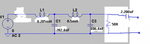
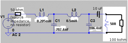
With 10 uF somewhere in between a 50 ohm source and a 50 ohm load, the AC coupling time constant is 10 uF * (50 ohm + 50 ohm) = 1 ms, giving you a first-order roll-off below 159 Hz. I'm neglecting the impact of the other filter components now, but I think that's OK as they presumably only kick in above 20 kHz.
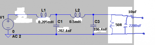
Its as I said before - 2200uF in series with the 50ohm but no need to have it in the signal path as in @MarcelvdG's drawing, rather put it between the 50ohm resistor and 0V.
If you prefer 10uF rather than 2200uF it might work but you're the design authority for that change, not me
If you prefer 10uF rather than 2200uF it might work but you're the design authority for that change, not me
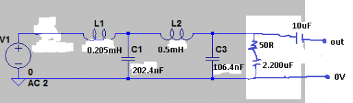
Yes your schematic looks correct. The 2200uF is in circuit so that there's not a DC current flowing through the 50R resistor which is just wasteful. We still need to terminate the filter at AC (20Hz and up), where the 2200uF looks very low impedance so barely affects the 50R loading.
- Status
- This old topic is closed. If you want to reopen this topic, contact a moderator using the "Report Post" button.
- Home
- Source & Line
- Digital Line Level
- low pass filter for DSD