Well, maybe just the oscillator board(s)? Power supply? I dunno, just throwing ideas out there.
Sure maybe when it's said and done.
Scotts (?) Thx-RNMarsh
No that was Mr. Brisbois' exactly in fact except for the op-amp. My oscillator is the one Mr. Bateman re-published, it uses an SSM VGA and rms detector.
I suspect the performance of the Brisbois oscillator would be highly compromized (or take several minutes to settle) at 100Hz.
Okay so we'll continue here.
All the oscillator measurements taken have been with large averaging. I turned the averaging down to 1 and found the 2nd H rising to a little over -120dB and then dropping back down disappearing into the noise floor. Rather odd behavior. I notice HP use shielded cable for just about ever connection in the oscillator except for the leads going to the level pot, the frequency vernier and few other minor connections. I twisted the wires for the level trim pot and the effect stabilized. Even at 1KHz the radiation is strong and somehow is causing some beating. The answer to this is to use shielded cable or coax on all the controls.
I only removed components necessary to disable the circuit from the op amp U1 and I think removing any dangling components will help with radiated effects.This and a really good cleaning of the board should do it I think. The pots are old and beyond cleaning, get rid of them.
I replaced A1U3 with a LME49710. I would have used a 1468 but they don't load well into 600 ohms. It raises the distortion.
I'm going to try converting the buffer to an inverting type because I think the the distortion will be better and the circuit impedance less sensitive to loading effects. This way we can change the gain a bit for the level vernier and if that doesn't work then leave the pot as an attenuator.
Cheers,
Last edited:
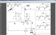
I'll be using the OPA1654 Quad opamp for the filters- also on order. -RNMRick -- note that the quad amp used by HP for the filters is a real stinker noise wise, and will need to be replaced with something much quieter if you're going to get lower distortion readings on the meter.
[the original IC is a quad of 741 opamps !! Designers must have been drunk that day.]
Last edited:
I'll be using the OPA1654 Quad opamp for the filters- also on order. -RNM
[the original IC is a quad of 741 opamps !! Designers must have been drunk that day.]
LOL.
You've got one in the oscillator as well and two in the auto null circuits.
[The original IC is a quad of 741 opamps! Designers must have been drunk that day.]
Well, if they just pass control signals or the residual, why not..?
Samuel
Well, if they just pass control signals or the residual, why not..?
Samuel
Some are for cntrol, thats fine.
For .002% thd apparently it didnt matter. .0002 is another matter. The quad is used for the various filters (400, 30K, 80KHz) and contribute to increased noise in the monitored residual which limits the ability to read/measure very low level harmonics. Any additional thd may have been low compared to the residual but now it isnt low enough. Its a few DB at a time. Only newer opamps and passive parts allows for changes squeezing out more performance; the over-all fundemental design concept seems fine. So maybe they werent drunk after all? That was a bit harsh, I suppose.
Last edited:
Some are for cntrol, thats fine.
For .002% thd apparently it didnt matter. .0002 is another matter. The quad is used for the various filters (400, 30K, 80KHz) and contribute to increased noise in the monitored residual which limits the ability to read/measure very low level harmonics. Any additional thd may have been low compared to the residual but now it isnt low enough. Its a few DB at a time. Only newer opamps and passive parts allows for changes squeezing out more performance; the over-all fundemental design concept seems fine. So maybe they werent drunk after all? That was a bit harsh, I suppose.
Hi Rick,
I think the noise we are after is way out of sight for us. Possibly in the MHz. We need a wide band spectrum analyzer to see it. Much wider than what you have. Although I know someone that just got a PI for there TEK frame that might do it.
I also have access to an RF spectrum analyzer at work but it is 50 or 75 ohm input Z.
That's a hard load for what we have. I suppose I could use a buffer.
In my experience active filters are just noisy; don't know if it has to be that way... but for me the crucial filters are 400Hz and 80kHz (for LP, I'd rather have 10kHz and 100kHz, and may make those changes). In the 339, the 80k filter is the worst for added noise -- the 400Hz HP actually doesn't seem to add much to the baseline noise, and it really is needed to control the line-related spurs.
The guy with the recently acquired 7L5 won't be looking inside his 339 until after the holidays and on into the new year a ways, maybe February. Sorry folks, just how it is. This isn't such a deal for David, who wants his 339 to be a front end for spectrum analysis, but for those who just want to see a believable meter reading, it's a different matter. Still, david could benefit from the 400Hz HP.
The guy with the recently acquired 7L5 won't be looking inside his 339 until after the holidays and on into the new year a ways, maybe February. Sorry folks, just how it is. This isn't such a deal for David, who wants his 339 to be a front end for spectrum analysis, but for those who just want to see a believable meter reading, it's a different matter. Still, david could benefit from the 400Hz HP.
In my experience active filters are just noisy; don't know if it has to be that way... but for me the crucial filters are 400Hz and 80kHz (for LP, I'd rather have 10kHz and 100kHz, and may make those changes). In the 339, the 80k filter is the worst for added noise -- the 400Hz HP actually doesn't seem to add much to the baseline noise, and it really is needed to control the line-related spurs.
The guy with the recently acquired 7L5 won't be looking inside his 339 until after the holidays and on into the new year a ways, maybe February. Sorry folks, just how it is. This isn't such a deal for David, who wants his 339 to be a front end for spectrum analysis, but for those who just want to see a believable meter reading, it's a different matter. Still, David could benefit from the 400Hz HP.
Hi Dick,
I am referring to the noise when the filters are switched out, bypassed.
The quad op amp for the meter's filters etc. was changed out about a year and a half ago with no improvement at all. There is more to this.
A brick wall filter such as what's in the 3581C would do well.
I think we might have some parasitic stuff going on.
Cheers,
In the 339, the 80k filter is the worst for added noise.
With the 80 kHz filter, the residual shows more noise because the measurement bandwidth is greater, not because the low-pass filter adds any significant noise! In a well-designed analyzer, there is, depending on the range, 20-60 dB gain ahead of the bandwidth-limiting filter. With this, it isn't hard to make its noise contribution entirely negligible.
I don't know the exact situation in the older HP analyzers under discussion, but I'd be surprised if they had fallen into such a basic trap.
Samuel
My point is that, looking at the monitor output with a spectrum analyzer, switching in the stock 80kHz filter raises the noise floor significantly over leaving it out, which should be the higher noise case. The effect is less pronounced with the 30kHz filter, thanks primarily to the much more restricted bandwidth, just as Sam points out.
Yes, getting rid of the noise that's running around post-notch is needed; but a filter that increases noise instead of reducing it, isn't really that helpful if you want some filtering before the ADC. You're right David, we have to reduce the broadband noise somehow, regardless of whether we want to read a meter or drive other gear.
Maybe Rick's filter amp swap-out will tell us something, as I think he's chosen the right amp for the filters... Can't remember David, which quad you used.
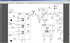
Passive changes only to Analyzer -
Without working on the source - davada has that covered.....
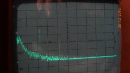
I added a socket for the quad filter and dropped in a TL074 as a place holder. Its still quieter than the original Quad IC. Then --> I changed the large value caps out with 105 degree C NP (non-polar) types and retuned for null. The reson for doing this is that lower esr means lower noise and deeper null. Also, the NP types have lower thd than the tant types in the first place. Now I can see some 5th at -145dB (!). Top of screen is -80dB. and 10dB/div. All filters IN.
Now, I am going to work on the sine wave source and start on those issues davada has done. Noted also that filter switch contacts must be very clean or contacts will raise thd a small but trouble-some amount. Thx-RNMarsh
Without working on the source - davada has that covered.....
I added a socket for the quad filter and dropped in a TL074 as a place holder. Its still quieter than the original Quad IC. Then --> I changed the large value caps out with 105 degree C NP (non-polar) types and retuned for null. The reson for doing this is that lower esr means lower noise and deeper null. Also, the NP types have lower thd than the tant types in the first place. Now I can see some 5th at -145dB (!). Top of screen is -80dB. and 10dB/div. All filters IN.
Now, I am going to work on the sine wave source and start on those issues davada has done. Noted also that filter switch contacts must be very clean or contacts will raise thd a small but trouble-some amount. Thx-RNMarsh
Attachments
Last edited:
339a grounding
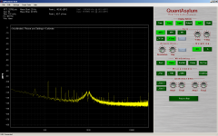
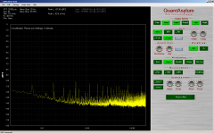
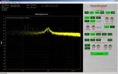
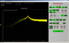
With just the QA400 connected to the 339a notch amp output.
The spectra looks like this.
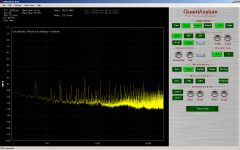
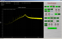
And with just the ground to my scope connected tot he ground post of the 339a monitor output the spectra looks like this.
I would suspect something wrong with the scope but I get RF parasitic oscillation just connecting the ground of my HP3581C to the ground post of the monitor output.
With just the QA400 connected to the 339a notch amp output.
The spectra looks like this.
And with just the ground to my scope connected tot he ground post of the 339a monitor output the spectra looks like this.
I would suspect something wrong with the scope but I get RF parasitic oscillation just connecting the ground of my HP3581C to the ground post of the monitor output.
Attachments
My point is that, looking at the monitor output with a spectrum analyzer, switching in the stock 80kHz filter raises the noise floor significantly over leaving it out, which should be the higher noise case. The effect is less pronounced with the 30kHz filter, thanks primarily to the much more restricted bandwidth, just as Sam points out.
Yes, getting rid of the noise that's running around post-notch is needed; but a filter that increases noise instead of reducing it, isn't really that helpful if you want some filtering before the ADC. You're right David, we have to reduce the broadband noise somehow, regardless of whether we want to read a meter or drive other gear.
Maybe Rick's filter amp swap-out will tell us something, as I think he's chosen the right amp for the filters... Can't remember David, which quad you used.
That op amp is deep. Wouldn't you know it, can't find a working flashlight around the house.
I think it was a quad low noise jfet type.
I think what we need to do is isolate each stage and look at them individually. With such a long chain it's hard to tell just exactly where the noise originates. Speculating is good but it not getting us anywhere. We might find everything is where it should be and the problem is fundamental to the design. I do know that there is large amount of high frequency noise viewed on my scope off the monitor output which significantly drops when either of the LP filters are switched in.
If we look at the schematic, we can see the post amplifier after the filters is the one that has a gain 100. This means that the filters noise is being amplifier by that amount. One could reason that there would be better SNR if the filters came after the x100 amp. There is a trade off here. With higher level we would see higher distortion from the filters and that would be added to the measurement. Instead HP went for the higher noise. It does satisfy there base line with the filter in.
We can test this by rearranging the filters and post amplifier. Make the x100 a preamplifier to the filters and see what happens.
But the bulk of the noise isn't coming from the filters it's from the analyzer it self. There is a huge difference in noise level between level mode and analyzer mode but both have the same scale.
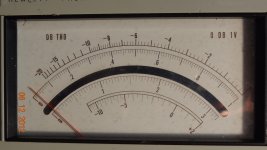
I just notice something. I have the 339a with just the oscillator connected to the analyzer.
The meter is reading near 0.004% with the LP filter off. The range is -80dB with 1Vrms at the notch filter input, what I've been using with all my measurements. With nothing changed from the above, when I connect the QA400 to the monitor output the meter pins at over full scale. Even with just the QA400 ground connected, the meter pins. With the LP filters switch in the meter goes to a reading of 0.0015%.
So what does everyone make of this. I say there is something very wrong with the grounding in this 339a
I am curious of why I don't see the HP function when the LP filters are switched out. THe HP filter has been in all this time.
Cheers,
We can test this by rearranging the filters and post amplifier. Make the x100 a preamplifier to the filters and see what happens.
But the bulk of the noise isn't coming from the filters it's from the analyzer it self. There is a huge difference in noise level between level mode and analyzer mode but both have the same scale.
I just notice something. I have the 339a with just the oscillator connected to the analyzer.
The meter is reading near 0.004% with the LP filter off. The range is -80dB with 1Vrms at the notch filter input, what I've been using with all my measurements. With nothing changed from the above, when I connect the QA400 to the monitor output the meter pins at over full scale. Even with just the QA400 ground connected, the meter pins. With the LP filters switch in the meter goes to a reading of 0.0015%.
So what does everyone make of this. I say there is something very wrong with the grounding in this 339a
I am curious of why I don't see the HP function when the LP filters are switched out. THe HP filter has been in all this time.
Cheers,
Attachments

Last edited:
Grounding problem
It seems I have misinterpreted the problem.
As it turns out this is a low frequency problem. The ground selector switch is not doing
a very good job of grounding the in chassis to the outer earth grounded chassis.
This can also trigger RF parasitic oscillation.
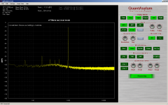
Look at the difference when I ground the inner chassis to the outer chassis with a small piece of wire.
The meter reading dropped 1.5 orders of magnitude with the LP filter out.
Seems more normal now at 0.004% reading LP filters out.
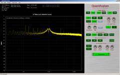
With the 80KHz filter in it reads 0.0018% and the 30KHZ the usual 0.0014%.
I can't get to the ground switch because all the set screws for all the knobs are frozen.
Nothing quite like a earth ground loop.
Cheers
It seems I have misinterpreted the problem.
As it turns out this is a low frequency problem. The ground selector switch is not doing
a very good job of grounding the in chassis to the outer earth grounded chassis.
This can also trigger RF parasitic oscillation.
Look at the difference when I ground the inner chassis to the outer chassis with a small piece of wire.
The meter reading dropped 1.5 orders of magnitude with the LP filter out.
Seems more normal now at 0.004% reading LP filters out.
With the 80KHz filter in it reads 0.0018% and the 30KHZ the usual 0.0014%.
I can't get to the ground switch because all the set screws for all the knobs are frozen.
Nothing quite like a earth ground loop.
Cheers
Attachments
Last edited:
- Home
- Design & Build
- Equipment & Tools
- Low-distortion Audio-range Oscillator