There is a notch filter topology that lends itself quite well to adjustment.
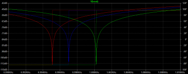
Horowitz & Hill call it bridged differentiator (3rd Ed., p. 415), and here is a simulation of a 1kHz version with three equal capacitors of 33nF each, tuned within a range of about 5Hz with a 200 ohm potentiometer.
Regrads,
Braca
Horowitz & Hill call it bridged differentiator (3rd Ed., p. 415), and here is a simulation of a 1kHz version with three equal capacitors of 33nF each, tuned within a range of about 5Hz with a 200 ohm potentiometer.
Regrads,
Braca
Attachments
It doesn't differ from the attenuation of the Twin-T topology. In my case, 10dB at the 2nd, and 6dB at the 3rd.Looking good. How much is the attenuation at 2kHz when set to 1kHz center frequency?
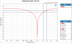
The second plot shows what happens if I only adjust the "R/2" of the T, for the same range of 31 ohms as in the plot before. The notch depth suffers much too hard for my liking, that's why I went the extra mile and used a bunch of relays.
Hi Lasse, I am trying to follow this interesting thread but stumbling upon your post leaved me a little confused, when you write "R/2" what resistor are you actually referring to in this schematic below?
Also, how big are the changes in resistor value for each curve drawn in the second picture and what is the resistor value in your notch filter, thank you.
It doesn't differ from the attenuation of the Twin-T topology. In my case, 10dB at the 2nd, and 6dB at the 3rd.
Seems like the bridged differentiator can also be made active and bootstrapped for a narrower notch. On a first sim I could achieve -0.3dB at 2nd harmonic for ~80dB notch depth with ideal values. The Twin-T can go at least down to 120dB with only -0.1dB at the 2nd - in simulation at least.
Don't have time now, but I'll investigate later.
Hi Lasse, I am trying to follow this interesting thread but stumbling upon your post leaved me a little confused, when you write "R/2" what resistor are you actually referring to in this schematic below?
Also, how big are the changes in resistor value for each curve drawn in the second picture and what is the resistor value in your notch filter, thank you.
I did not use the symmetrical schematic that you are referring to. If you were using only the upper half of that scheme, I'd be referring to R3.
The changes are made with 1R steps for almost 32R total (31R1 actually, leaving out the contact resistance of the relays for now). The resistance value for the T is about 16k1.
There used to be an extensive treatment of the Hall topology and its application by Kenneth Huhn:
http://www.kennethkuhn.com/electronics/
It was submitted to EDN for publication in 2012, but can not be retrieved in full from EDN's site any more (broken links to the formulas, etc.), and it is also not to be found on Kuhn's website.
A bootstrapped active version of the notch filter was described in that submission.
Regards,
Braca
The main question in this case is, what will be the input after the "balanced" device? In most cases you you'll be under the risk of big common mode voltage, if you don't use the GND reference.
If you mean to connect a balanced signal to a single-ended input, yes then one of the balanced signals goes to the se 'hot' input and the other to the 'local' ground at the se input which then is the reference.
I don't see a CM in this picture?
In this scenario you could use a single-ended twin-tee just before the se input. But you wouldn't use a pair of se twin-tees somewhere in the balanced line of course. You would then have a ground somewhere from the two se twin-tees and then again a ground at the se input. Inviting lots of problems.
If you are on a bal line, keep it that way as long as possible and do not re-introduce ground on the way
Jan
Bainter Notch Filter
We should also not overlook the Bainter active notch filter, described on page 619 in my second edition in the chapter on Audio Instrumentation. This filter uses only 2 R and 2 C, and they need not be precision matched. It can also be tuned with either R without compromising notch depth. As an active notch filter, it also is quite sharp, with minimal attenuation at the 2H frequency. Its disadvantage is that it uses 3 op amps. Mitigating this a bit is that none of the op amps has the fundamental signal on its non-inverting input, reducing the possibility of common-mode distortion from the op amps.
Cheers,
Bob
Here one more... I love here the noise figures 
https://www.edn.com/three-op-amp-state-variable-filter-perfects-the-notch/
https://www.edn.com/three-op-amp-state-variable-filter-perfects-the-notch/
Lots of interesting stuff! I'd love to build prototypes of every topology and compare them to each other...
Did another simulation run with the Bridged Differentiator in direct comparison to a Twin-T. Looks like it stacks up pretty well (the notch is almost equal for both) and is much easier to trim for a couple of Hz. Why didn't I knew that one before I started building the Twin-T? Now on to find its weaknesses.
The Bainter looks interesting too, but at a first glance I would say that it is much more demanding on opamp performance, quite like the State Variable. The bootstrapped Twin-T and Bridged Differentiator only need two buffers, which can be pretty much anything. Here a real world comparison would come in handy, as well as some deeper understanding of the circuits.
We should really have a Notch Filter Thread to show off all those topologies. Anybody dare to create one?
Did another simulation run with the Bridged Differentiator in direct comparison to a Twin-T. Looks like it stacks up pretty well (the notch is almost equal for both) and is much easier to trim for a couple of Hz. Why didn't I knew that one before I started building the Twin-T? Now on to find its weaknesses
.The Bainter looks interesting too, but at a first glance I would say that it is much more demanding on opamp performance, quite like the State Variable. The bootstrapped Twin-T and Bridged Differentiator only need two buffers, which can be pretty much anything. Here a real world comparison would come in handy, as well as some deeper understanding of the circuits.
We should really have a Notch Filter Thread to show off all those topologies. Anybody dare to create one?
Attachments
Here one more... I love here the noise figures
https://www.edn.com/three-op-amp-state-variable-filter-perfects-the-notch/
This is an interesting variation on the state variable notch filter. The more conventional one, as used in my distortion analyzer, takes the difference of the input and BPF outputs with a 4th op amp. In fairness, for the normally expected low impedance output, this is also really a 4 op-amp filter.
In the conventional state variable notch, the depth of the notch depends on the BPF gain being precisely unity at the center frequency, since a subtraction is involved. In a conventional THD analyzer, this is taken care of by the auto-tune amplitude control circuit. In this filter, it looks like the notch depth is naturally low without amplitude tweaking or matching, but may be limited by some other small effects. Notch depth in a THD analyzer with autotune should be 110 dB or more.
I think the author of the article may have slightly mis-led in saying that tuning and Q interact in the Bainter filter. For maximum notch depth, the resistor in the Bainter filter that sets Q is often at or near infinity to obtain the deepest and narrowist notch. That's the way we want it in most applications.
Cheers,
Bob
It was submitted to EDN for publication in 2012, but can not be retrieved in full from EDN's site any more (broken links to the formulas, etc.), and it is also not to be found on Kuhn's website.
If you still have does broken links, please go to Wayback Machine and check those links and get back here with the result.
Anybody dare to create one?
Here we go… Admin please move latest entres to this thread …
https://www.diyaudio.com/forums/equipment-and-tools/348464-measuring-ldo-passive-active-notches-filter.html#post6054408
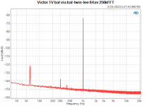
... and this is Viktor's 1kHz oscillator, 1V balanced out, via de bal-twin-tee. First independent verification I have seen that his oscillator is clean down to at least -150dB. Viktor, chapeau!
The bal-twin-tee is not yet in its intended enclosure, hence he mains spurs.
Jan
The bal-twin-tee is not yet in its intended enclosure, hence he mains spurs.
Jan
Attachments
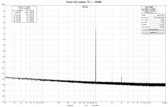
I find that it is clean to down below -155dB (3H) and for 2H even -160dB.
Balanced Victor with notch filters from Victor, in balanced configuration.
Victor output is 14.6dBV, full scale is -20dBV, and notch attenuation at 2H and 3H are 9.4 dB and 5.4 dB, respectively.
Balanced Victor with notch filters from Victor, in balanced configuration.
Victor output is 14.6dBV, full scale is -20dBV, and notch attenuation at 2H and 3H are 9.4 dB and 5.4 dB, respectively.
Attachments
- Home
- Design & Build
- Equipment & Tools
- Low-distortion Audio-range Oscillator