Not better because then you can't use it single ended anymore.Converting the twin-tee for bal is much better (and easier and cheaper) than using two single ended ones.
All Rs and Cs now have equal values ;-)
Jan
Not easier unless you have all the parts and PCBs.
Not cheaper that the parts bought from Mouser with shipping.
Converting the twin-tee for bal is much better (and easier and cheaper) than using two single ended ones.
All Rs and Cs now have equal values ;-)
Jan
Hi Jan,
It is unclear whether this circuit works for single-ended in and single-ended out, or for just one or the other. I must admit that I did not try to analyze it.
Cheers,
Bob
I am currently building an active Twin-T with a sharp and deep notch, so the attenuation at the 2nd will be minimal (0.1dB or something). To be able to keep the notch spot-on, I add a 5-bit relay switched threefold trim resistor (registered trademark). This will allow me to shift the notch by about 1.5Hz for 1kHz center frequency, with just a single rotary encoder. Hope this works...
Are you saying that each step of the rotary encoder shifts it 1.5 Hz, or that the entire range of all 32 steps of the rotary encoder gives a 1.5 Hz shift?
Your approach is obviously the right way to accomplish a shift with fine granularity and minimal notch degradation. However, I have found that just trimming the shunt resistor in the twin-T network will shift the notch a little bit with quite small degradation in notch depth. I have not simulated that effect (e.g., notch depth degradation vs. frequency shift), but it might be useful to know in deciding what approach to use in a given circumstance.
Cheers,
Bob
The entire range of the circuit I'm building according to my simulations will allow a shift of ca. 1.8Hz, with a step size of ca. 0.06Hz (or 60mHz) for each of the 32 steps.
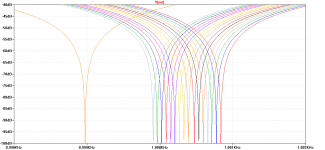
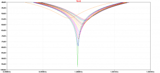
Here are two simulation plots. The first one shows what I'm expecting to achieve. This is with capacitors of 10nF matched to within 2pF and pretty much ideal resistor values; in reality I expect to get around 80dB notch depth, probably even better with an additional pF here and there.
The single steps cross at around 72dB notch depth, which should be some kind of worst performance limit I suppose.
The second plot shows what happens if I only adjust the "R/2" of the T, for the same range of 31 ohms as in the plot before. The notch depth suffers much too hard for my liking, that's why I went the extra mile and used a bunch of relays.
Attachments
Hi Jan,
It is unclear whether this circuit works for single-ended in and single-ended out, or for just one or the other. I must admit that I did not try to analyze it.
Cheers,
Bob
It's pure for balanced mode. The fact that all values are the same helps to make it completely symmetrical which is of importance for keeping max CMRR for balanced connections, but of course two single-ended ones will also work.
Will put it in a nice box with XLR connectors. I also have a single-ended one, also in a nice box with BNC connectors ;-)
Jan
Last edited:
The entire range of the circuit I'm building according to my simulations will allow a shift of ca. 1.8Hz, with a step size of ca. 0.06Hz (or 60mHz) for each of the 32 steps.
Here are two simulation plots. The first one shows what I'm expecting to achieve. This is with capacitors of 10nF matched to within 2pF and pretty much ideal resistor values; in reality I expect to get around 80dB notch depth, probably even better with an additional pF here and there.
The single steps cross at around 72dB notch depth, which should be some kind of worst performance limit I suppose.
The second plot shows what happens if I only adjust the "R/2" of the T, for the same range of 31 ohms as in the plot before. The notch depth suffers much too hard for my liking, that's why I went the extra mile and used a bunch of relays.
Lasse, are you sure it is worth going trough all this just to have a minimal attenuation of the 2nd? Are you trying to get to the point where there is no correction necessary for the 2nd?
Jan
Lasse, are you sure it is worth going trough all this just to have a minimal attenuation of the 2nd? Are you trying to get to the point where there is no correction necessary for the 2nd?
I will see whether it was worth it afterwards, but it is fun anyway!
There won't be any correction necessary, with the 2nd being 0.13dB down in simulation. This can even be bettered with a simple resistor divider (could be made adjustable with a pot), but that will also make the notch even narrower, which might become problematic at one point.
So how do you prevent your active notch from adding any distortions above say -140dB ?
I don't know. I will probably take what I can get and be content with it. The vicnic alone is already a lot better than what my humble Juli@ can resolve, so if the Twin-T helps me to get some better readings, I'm fine with that.
Maybe I can compare measurements with and without the Twin-T, and see by how much they differ?
> It's pure for balanced mode.
The assumption is that the two inputs are perfectly equal but opposite.
What would happen if they are not 100% symmetrical ?
Patrick
Not my assumption Patrick! Balanced is not the same as symmetrical. In fact, signal symmetry is irrelevant for a balanced connection. That is at the heart of it's advantage.
Jan
What would happen if they are not 100% symmetrical ?
Janneman could simply set the value of E2 to something like 0.9999 for some slight imbalance and check out the result.
LTspice can also do monte carlo for part tolerances. Use something like {mc(10n,10m)} for 10nF with +-1% tolerance (1=100%, 0.1=10%, 0.01=10m=1% variance). Simulate at least 8 runs with a .step command to see some variation in the plots.
Janneman could simply set the value of E2 to something like 0.9999 for some slight imbalance and check out the result.
The only change would be in output differential level. The filter shape and fundamental suppression do not change.
In fact you could ground one side of the input and set the other to double level and nothing would change on the output differential voltage or response shape.
Jan
Last edited:
The entire range of the circuit I'm building according to my simulations will allow a shift of ca. 1.8Hz, with a step size of ca. 0.06Hz (or 60mHz) for each of the 32 steps.
Here are two simulation plots. The first one shows what I'm expecting to achieve. This is with capacitors of 10nF matched to within 2pF and pretty much ideal resistor values; in reality I expect to get around 80dB notch depth, probably even better with an additional pF here and there.
The single steps cross at around 72dB notch depth, which should be some kind of worst performance limit I suppose.
The second plot shows what happens if I only adjust the "R/2" of the T, for the same range of 31 ohms as in the plot before. The notch depth suffers much too hard for my liking, that's why I went the extra mile and used a bunch of relays.
Thanks for doing these sims. Looks good.
Cheers,
Bob
The only change would be in output differential level. The filter shape and fundamental suppression do not change.
Did a quick simulation and can confirm this.
Thanks for doing these sims. Looks good.
You're welcome. When I have the prototype up and running to compare it to the simulation, I will open up another thread to show the results, including simulation files, schematic, matching procedure for parts, ASM for the uC and all that stuff. Maybe it will inspire others to build one for themselves - I won't be building them in numbers like Victor does with his oscillator though
.Did a quick simulation and can confirm this.
Thanks. It also makes it very clear that using a pair of single-ended twin-tees in a balanced line would destroy the defining advantage of balanced, as you now re-introduce ground as a reference. Bad Idea.
Jan
The main question in this case is, what will be the input after the "balanced" device? In most cases you you'll be under the risk of big common mode voltage, if you don't use the GND reference.Thanks. It also makes it very clear that using a pair of single-ended twin-tees in a balanced line would destroy the defining advantage of balanced, as you now re-introduce ground as a reference. Bad Idea.
Jan
The main question in this case is, what will be the input after the "balanced" device? In most cases you you'll be under the risk of big common mode voltage, if you don't use the GND reference.
Yes, a ground connection should be provided for just in case there is a large common-mode voltage.
Thanks. It also makes it very clear that using a pair of single-ended twin-tees in a balanced line would destroy the defining advantage of balanced, as you now re-introduce ground as a reference. Bad Idea.
I just use the Victor LDO (balanced output) using a dual active T-Notch… y no problemo
IMHO the issues rises rather with none active vs. active operation. This means, on active of the rising noise floor (R/C value dependent) at 1kHz (as my a 1kHz notch) and on none active the attenuation into noise floor as the noise bell from the LDO and shifting the Har's into noise floor too.
So I am interested only in active notches, but with an other topologie as the classic feedback T-Notch who acts as a classic loop into the notch.
just my 2 cents
Hp
- Home
- Design & Build
- Equipment & Tools
- Low-distortion Audio-range Oscillator