Is there a circuit for David's oscillator?
No, not at this time. Maybe we can get the block diagram put up. But it will require more money and time to produce. I would like to help get it made as a kit or finished product after it is ready.
THx-RNMarsh
Question: Would a steel chassis help in reducing picked up hum current?
Also, I've always wondered, would adding a DC magnetic field onto the case help in reducing magnetic pick up by saturating the magnetic capability of the case? Neodymium magnets are cheap.
What effect would a static magnetic field have on an alternating magnetic field?
Easy to try.
You might try lining the steel case with aluminum foil. It will reduce the hysteresis effects a bit. Contact cement or spray glue work well for that.
I suspect that if you put a magnetic bias on the steel the shielding will be less effective. With MU metal shields they have to be annealed and demagnetized after forming to work properly. In forming or even if dropped they pick up a bit of a PM field and do not work as well.
I suspect that if you put a magnetic bias on the steel the shielding will be less effective. With MU metal shields they have to be annealed and demagnetized after forming to work properly. In forming or even if dropped they pick up a bit of a PM field and do not work as well.
Is there a circuit for David's oscillator?
Hi Bonsia,
There is. I haven't published it in whole. I did upload a PDF of the ALC page of the schematics in a conversation a few month ago. It's on this thread.
Of course boards are done but I've made some minor changes and upgrades to the art.
I like to build a board from these changes to make sure there isn't any 'oops' before offering to others.
The design isn't complete. It still needs a post amplifier with same or better performance.
Or at least a buffer if used as is. My vision is to make it more like a complete finished product at the circuit board level. Oscillator, post amplifier and attenuator.
If there is minor interest, which there is, things are complete enough PCB art, schematics etc. I would just have to do a BOM and mechanical drawings. Some lending a hand with testing the software are having a bit of trouble with the newer Win7/8. It's not a software problem but it is a problem with Microsoft and .Net current versions. Or I just haven't made it easy enough to install the software. A bit polishing here is required.
With out a buffer there can be a bit of parameter shifting from loading the oscillator core. Slight shifts in frequency and possibly level. A buffer/post amplifier will remove the sensitivities by decoupling. A bit more gain followed by passive attenuation can improve the SNR and make the oscillator more useful for some things. I think Richard is interested in component testing. So am I.
Would Mu metal help for shielding?
I was thinking about trying some of the EMI/RFI sheets I've seen available from Digikey.
I believe these are absorbing materials.
If you can do that math in your head, I am truly impressed!
No no--I'm teaching Decibels in one of my courses, know the formulas by heart and am pretty good at giving order-of-magnitude estimates, but that was my pocket calculator.
")
Samuel
You might try lining the steel case with aluminum foil. It will reduce the hysteresis effects a bit. Contact cement or spray glue work well for that.
I suspect that if you put a magnetic bias on the steel the shielding will be less effective. With MU metal shields they have to be annealed and demagnetized after forming to work properly. In forming or even if dropped they pick up a bit of a PM field and do not work as well.
PM field?
No no--I'm teaching Decibels in one of my courses, know the formulas by heart and am pretty good at giving order-of-magnitude estimates, but that was my pocket calculator.
Samuel
I had to run out to the drug store and buy new batteries for my calc.
How can they charge $12.00 for two 2032's?
Samuel, Thanks it was a bit scary to think anyone could do powers in their head to that degree of accuracy!
David, Permanent Magnet. I buy 2032's from Mouser, adding then to an order to beat shipping. For what you paid they would have sold you 50! I buy ten at a time and enough folks know that they don't last a year. As to shielding what is good for EMI is not always good for magnetic fields.
The problem with magnetic fields is that virtually everyone has AC power wiring, unless it is twisted pair, it will produce a magnetic field when current flows. (A twisted pair just emits much less.) At the levels Dick is measuring that field is what could be causing his readings. As it is large source size his gear is effectively inside the field and so shielding has to completely surround the gear. The good news is that small openings in the shield are not as critical as they would be for higher frequencies.
My shop is wired with twisted pair inside conduit and I still see it!
Samuel, Thanks it was a bit scary to think anyone could do powers in their head to that degree of accuracy!
David, Permanent Magnet. I buy 2032's from Mouser, adding then to an order to beat shipping. For what you paid they would have sold you 50! I buy ten at a time and enough folks know that they don't last a year. As to shielding what is good for EMI is not always good for magnetic fields.
The problem with magnetic fields is that virtually everyone has AC power wiring, unless it is twisted pair, it will produce a magnetic field when current flows. (A twisted pair just emits much less.) At the levels Dick is measuring that field is what could be causing his readings. As it is large source size his gear is effectively inside the field and so shielding has to completely surround the gear. The good news is that small openings in the shield are not as critical as they would be for higher frequencies.
My shop is wired with twisted pair inside conduit and I still see it!
Fortunately the calculator is an HP33s and the batteries will last for two years.
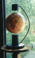
There was, or possibly still, is a company called Pacific levitation in Vancouver BC. They produced a novelty product of a levitated globe. It sensed the velocity of the falling globe and servo'ed an electromagenet keeping the globe afloat. They did all this with two TL082 op amps and supporting power circuitry.
Could a magnetic field be sensed, amplified and nulled using something like this.
Would a hall effect sensor be sensitive enough to do this. or do they act more like a switch. I've never used them.
Or maybe something more like a TV degaussing coil could sense and react at the same time.
The globe.
I see they are still around. Levitating trains
Attachments
Last edited:
I see some confusion on how shielding works here. It is actually a common problem and one of the reasons the EMI courses are popular even if expensive. I'm sure there are many watchers who would appreciate a quick introduction.
Magnetic shielding works differently from electrostatic shielding. With a magnetic field the goal is to provide a path around the shielded circuit that will shunt the external field so it doesn't pass through your device. John Curl's SOTA "piglet" preamp is a excellent example of simple implementation. It was a steel tube maybe 1/8" thick that the circuit was inside of. The steel was thick enough and magnetically soft enough that pretty much all the external field would concentrate in the steel and none would be inside. The core principle is that the magnetic shield is a pretty complete housing and with generous overlapping of seams. Welded seams can degrade the magnetic properties enough to degrade the shielding. If its magnetized the available flux before saturation gets used up and then it becomes transparent to the external field. Similar to a saturated cored inductor: the inductance drops to that which the coil would have without the core.
An electrostatic shield is used to create a constant electrostatic potential around the circuit at a known fixed potential to the internal circuit. it needs to be a conductive bubble around the circuit. Holes allow the external potential to affect what is inside. At RF the wavelengths matter as to the size of the holes. Long seams that are not electrically connected with an emi gasket can let in RF and are even used as antennas in some cases.
For this project a cake tin (steel) if big enough may work quite well. The walls will be thick enough to shunt a smaller field and have enough overlap to be continuous.
A sheet of steel will do very little since the wavelengths are long and will easily wrap around a panel. The RF absorber can help reduce RF radiation close to a source but won't do much for audio frequency radiation.
I could not find any quick intros but here are some background readings:
http://www.analog.com/static/imported-files/tutorials/MT-095.pdf
EMC EMI RFI ESD | EDN
LearnEMC: Shielding Theory
I met the engineer at a toast master's meeting. He explained the operation giving a speech.
We had a large scale version of this at Vancouver's science and technology center. That's where we dug into the control circuitry. The science and technology center is shaped like a golf ball, a left over from expo 86. I would more impressed if they levitated the building. $50,000 for the large globe version.
We had a large scale version of this at Vancouver's science and technology center. That's where we dug into the control circuitry. The science and technology center is shaped like a golf ball, a left over from expo 86. I would more impressed if they levitated the building. $50,000 for the large globe version.
Last edited:
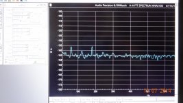
As I said yesterday..... I checked the single-end/coax for Common-Mode utility power field coupling into the cable. There was no observable change. So, now I have eliminated all but the shielding. Next up shielding affect.

Along with distance from powered equipment, the steel box the oscillator was put into did the most good.

From my plan yesterday, a 1/16th inch thick steel enclosure [isolated from the prototype and the batteries] was grounded separately to the A-P chassis ground near the input. Power supply and no other cables going in or out --- just the osc output coax. [A-P not grounded to utility ground]
And 1/8th steel box should do it.
THx-RNMarsh
Ignor thumbnail below... dont know how to remove it.
Along with distance from powered equipment, the steel box the oscillator was put into did the most good.
From my plan yesterday, a 1/16th inch thick steel enclosure [isolated from the prototype and the batteries] was grounded separately to the A-P chassis ground near the input. Power supply and no other cables going in or out --- just the osc output coax. [A-P not grounded to utility ground]
And 1/8th steel box should do it.
THx-RNMarsh
Ignor thumbnail below... dont know how to remove it.
Attachments
Last edited:
I see some confusion on how shielding works here. It is actually a common problem and one of the reasons the EMI courses are popular even if expensive. I'm sure there are many watchers who would appreciate a quick introduction.
Magnetic shielding works differently from electrostatic shielding. With a magnetic field the goal is to provide a path around the shielded circuit that will shunt the external field so it doesn't pass through your device. John Curl's SOTA "piglet" preamp is a excellent example of simple implementation. It was a steel tube maybe 1/8" thick that the circuit was inside of. The steel was thick enough and magnetically soft enough that pretty much all the external field would concentrate in the steel and none would be inside. The core principle is that the magnetic shield is a pretty complete housing and with generous overlapping of seams. Welded seams can degrade the magnetic properties enough to degrade the shielding. If its magnetized the available flux before saturation gets used up and then it becomes transparent to the external field. Similar to a saturated cored inductor: the inductance drops to that which the coil would have without the core.
An electrostatic shield is used to create a constant electrostatic potential around the circuit at a known fixed potential to the internal circuit. it needs to be a conductive bubble around the circuit. Holes allow the external potential to affect what is inside. At RF the wavelengths matter as to the size of the holes. Long seams that are not electrically connected with an emi gasket can let in RF and are even used as antennas in some cases.
For this project a cake tin (steel) if big enough may work quite well. The walls will be thick enough to shunt a smaller field and have enough overlap to be continuous.
A sheet of steel will do very little since the wavelengths are long and will easily wrap around a panel. The RF absorber can help reduce RF radiation close to a source but won't do much for audio frequency radiation.
I could not find any quick intros but here are some background readings:
http://www.analog.com/static/imported-files/tutorials/MT-095.pdf
EMC EMI RFI ESD | EDN
LearnEMC: Shielding Theory
I'm so glad that at least someone was able to stay awake through magnetism in physics.
The application of physics is far more interesting.
see my above... #3813. Completed earlier this morning.
BTW - this morning I went out and bought a small 20gal garbage can with lid. That is what I put the osc and batteries inside. Galvanized steel.
comment please. Now I can go back and measure distortion without separating out all the artifacts from the DUT harmonics.
-Richard
BTW - this morning I went out and bought a small 20gal garbage can with lid. That is what I put the osc and batteries inside. Galvanized steel.
comment please. Now I can go back and measure distortion without separating out all the artifacts from the DUT harmonics.
-Richard
Last edited:
see my above... #3813. Completed earlier this morning.
BTW - this morning I went out and bought a small 20gal garbage can with lid. That is what I put the osc and batteries inside. Galvanized steel.
comment please
-Richard
I might add that the oscillator enclosure is made from double sided FR4 with an aluminum framework and was intended as a temporary enclosure.
see my above... #3813. Completed earlier this morning.
BTW - this morning I went out and bought a small 20gal garbage can with lid. That is what I put the osc and batteries inside. Galvanized steel.
comment please. Now I can go back and measure distortion without separating out all the artifacts from the DUT harmonics.
-Richard
I would never have thought of that. I use one for dog food. It has the overlap even on the lid to work. Somehow its appearance can be said to be "unpreposessing" and not setting high expectations for the contents. Maybe ideal for audio?
There can be a legitimate issue if AC currents from the DUT get close to the can. The hysteresis of the steel can cause distortions. That should be manageable.
HaHaHa. I think it might catch on... one issued with each FFT system. Available everywhere and cheap enough. Paint it to match the room colors. Tie a ribbon on the lid handle.
All the tests I did were only as proof in that each one was like a Go-No_Go test for the direction to proceed in finding the source(s). They are quick experiments. Now, I fully expect to have a final product with a steel shell. About an inch seperation from any circuity will be fine. Insulated stand-offs? A box within a box.
THx-RNMarsh
A set of nested cans would be even better -- a smaller inside a larger. "Mild", ie soft steel is good, "tin" is not if real, and aluminum, although loosely magnetic, is not good for mag shielding. Nor is copper, obviously, so it's soft steel or nothing for us.
There are some small office waste cans that people are using to make Mac Pro hacks out of. I still favor old steel Christmas cookie and candy tins when I can find them, although I don't like the round or odd shaped ones. Large steel cans such as giant economy size stew or chili cans work well if you use the edge of the rim type opener -=- the cut lid fits pretty tight and can be quickly soldered shut with the right acid flux paste.
There are some small office waste cans that people are using to make Mac Pro hacks out of. I still favor old steel Christmas cookie and candy tins when I can find them, although I don't like the round or odd shaped ones. Large steel cans such as giant economy size stew or chili cans work well if you use the edge of the rim type opener -=- the cut lid fits pretty tight and can be quickly soldered shut with the right acid flux paste.
Hi Bonsia,
There is. I haven't published it in whole. I did upload a PDF of the ALC page of the schematics in a conversation a few month ago. It's on this thread.
Of course boards are done but I've made some minor changes and upgrades to the art.
I like to build a board from these changes to make sure there isn't any 'oops' before offering to others.
The design isn't complete. It still needs a post amplifier with same or better performance.
Or at least a buffer if used as is. My vision is to make it more like a complete finished product at the circuit board level. Oscillator, post amplifier and attenuator.
If there is minor interest, which there is, things are complete enough PCB art, schematics etc. I would just have to do a BOM and mechanical drawings. Some lending a hand with testing the software are having a bit of trouble with the newer Win7/8. It's not a software problem but it is a problem with Microsoft and .Net current versions. Or I just haven't made it easy enough to install the software. A bit polishing here is required.
With out a buffer there can be a bit of parameter shifting from loading the oscillator core. Slight shifts in frequency and possibly level. A buffer/post amplifier will remove the sensitivities by decoupling. A bit more gain followed by passive attenuation can improve the SNR and make the oscillator more useful for some things. I think Richard is interested in component testing. So am I.
Sounds good. I'll take one if you make then available.
- Home
- Design & Build
- Equipment & Tools
- Low-distortion Audio-range Oscillator