Not to thread-hijack -- but parenthetically, the Edison National Museum reopened last year after a huge refurbishment -- I know that when folks come to the US they have limited time to browse places like this, (and it's in West Orange NJ which takes about hour to get to from NYC) -- but it's worth the trip if you have interest in the history of engineering.BTW 2: I've scanned a page from the May 2013 issue of "Scientific American" about simulation. I suppose you prefer the way Thomas Edison did it.
The point is that, whatever you do, the noise will increase with decreasing frequency. There are some laws that are impossible to avoid.
I/we know this... just make it lower than is done in the past for better overall performance.
I have attached measurements of a low noise oscillator.
BTW 1: Sorry to say it Richard, but simulation is useful and necessary if one is to design new circuits and explore new ideas. To swap opamp's has nothing to do with designing new things.
Dry your tears. No need to feel sorry --- I/we know this also. I wanted to see what had been done and from that, where to go next. Useful for the DIY'er on a budget, too.
SIMs are fine for eploring new ideas. I use MicroCap when needed.
Stein
One thing that might help is to roll off the freqs below 10hz going to the DUT as they only contribute to unwanted jitter/freqs.
Thx-RNmarsh
Last edited:
@ Scott: could you check the spice models of the SSM2212 and SSM2220? are they correct when it comes to noise simulation? RB seems to be a bit optimistic. I prefer and use mostly MEXTRAM models for small signal BJT's, but I suppose it's too much to ask for.
(Scott, when I look at the data sheets for these transistors, I wonder if there are some among you who doesn't know the difference between NPN and PNP)
Stein

We use MEXTRAM but most/many? customers don't. I've been there on those datasheets, but can't decree a change.
EDIT - Yikes you made me look, the stupid noise graphs with the physically impossible bumps are still there. Yes the rbb listed would give .65nV at 1mA not .85 (the spec).
Last edited:
The point is that, whatever you do, the noise will increase with decreasing frequency.
I don't know how exactly you define noise in an oscillator, but what we (I?) have discussed is reducing THD+N for a given bandwidth (e.g. 22 kHz). And that surely decreases with decreasing frequency (at least as a general statement, the exact behaviour is pretty complex), as the equivalent noise bandwidth of various sources is proportional to oscillation frequency.
Samuel
Both true.... noise increasing at lower end/freqs (10Hz) from active circuitry (opamps etc) to be lowered and thd+n (22KHz BW) to be lowered. Different mechanisms and issues but both need to be reduced.
Thx-RNMarsh
What's an acceptable amplitude stabilization at 20 Hz?
Well, having the advantages of DIY you can set the specs! But it is not entirely clear what you mean by amplitude stability--flatness with reference to 1 kHz, random amplitude variations, slow drift..?
Samuel
Well, having the advantages of DIY you can set the specs! But it is not entirely clear what you mean by amplitude stability--flatness with reference to 1 kHz, random amplitude variations, slow drift..?
Samuel
Amplitude variation of 0.05dB over 2 seconds from peak to trough and about 4 seconds for a complete cycle. Not referenced to any other frequency.
It's actually a less than 0.05dB but I'm going to call it that.
Last edited:
Well, having the advantages of DIY you can set the specs! But it is not entirely clear what you mean by amplitude stability--flatness with reference to 1 kHz, random amplitude variations, slow drift..?
Samuel
Yes we can set our own specs. The question is a comparative one.
I haven't looked that closely at other oscillator at this frequency.
Amplitude variation of 0.05dB over 2 seconds from peak to trough and about 4 seconds for a complete cycle. Not referenced to any other frequency.
It's actually a less than 0.05dB but I'm going to call it that.
And how do you measure that? Its the gray area where thermal converters don't work. Most DVM's with good accuracy need averaging for low frequencies. The averaging hides the fluctuations. KH used a 7A13 to monitor the peaks to test cycle to cycle stability.
And how do you measure that? Its the gray area where thermal converters don't work. Most DVM's with good accuracy need averaging for low frequencies. The averaging hides the fluctuations. KH used a 7A13 to monitor the peaks to test cycle to cycle stability.
I'm watching it on the FFT with no averaging at 96k and 8192 points.
I can see the variation on the scope using the 7A22 with DC offset to see the peak at 20mV/div.
I don't use a DVM for this kind of measurement.
Here are some amplitude noise measurements I've run several years back where I've started to look into oscillator design:
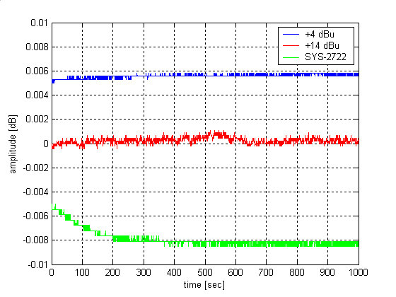
As I'm looking at the graph again, I'm pretty sure the +4 dBu and +14 dBu (which denotes the oscillator operating level) labels are interchanged.
This is for a SVF oscillator with sin^2 + cos^2 level detector (AD633), at 1 kHz. For the +4 dBu plot (red, mis-labeled as +14 dBu) the noise contribution of the squarers are clearly visible. At +14 dBu that's gone, but instead there was much more residual ripple from secondary effects (probably mostly nonlinearity) in the two multipliers.
As far as I recall I had to use the slowest integration time of the SYS-2722 RMS meter for these measurements, and average several readings for each data point. But that's long time ago.
Samuel
davada.... do you have a 7A13 plugin for your Tek scope?
Wouldnt you know it? I have a 7A13 plugin. Do you need to borrow it?
Thx-RNMarsh
I guess I do need one. I would buy one if you know a source. I don't trust the EBay guys.
I dug my old 7A12 which has a much greater dc offset range. Managed to get a measurement before it crapped out.
I don't have the amplitude stability problem I thought.
The long term drift is 0.003dB and short term looked more like 0.00045dB.
I'll need to confirm this with better working equipment.
The long term drift is 0.003dB and short term looked more like 0.00045dB.
I'll need to confirm this with better working equipment.
52 PPM? Even the best thermal converters are only barely that accurate under pretty ideal conditions. DVMs can do that for DC but I don't trust them for AC to that accuracy. The HP 3458 best is 100 PPM for AC.
talking about difference between resolution or accuracy?
Detectable changes vs absolute levels?
just checking.
-RM
I was using low res to speed up the software. Sound card stuff and software is not meant for doing this. Perhaps something intended for this type of measure.
Scope is the best thing if I can get it into the range needed.
- Home
- Design & Build
- Equipment & Tools
- Low-distortion Audio-range Oscillator