Yeah, -ECdesigns- is known for keeping for himself the schematics and for avoiding any education of the readersthis sort of behaviour is unacceptable!

... come on man, try waking-up from the other side of the bed for once!
Sincerely yours,
M.
Why so attacking? I bought the DAC module and the first thing John did is mailed me the full schematic of the DAC. Should you share your design secrets from years off engineering to the world on a forum? I doubt. Japanese are reading too ;-) EC-Design is going commercial with the SD-card player. It's a complete modular system and the prices of the modules are IMHO within the (european) DIY range. On another thread he posted the schematic of the PSU. I personally have fun and respect what John shares of his knowledge on the forum.
He's joking. That is why he added the Joker.Why so attacking?
Quote:
-Why so attacking?
-He's joking. That is why he added the Joker.
Exact. I am -ECdesigns'- number one fan. Without him I would be still tweaking my OS DAC and without his endless technical posts
I would be even more ignorant...Sorry for the confusion.
M
He's joking. That is why he added the Joker.
Aha! sorry for the misunderstanding
Hi John,
You're complementary output powersupply -part (Module-Power Supply, of 16-01-2010) interests me. (had thoughts in this direction for years)
Can you tell us some more about it?
You mentioned that shunt-regulator would be limited...(I wanted to implement Sales or Ikflexer's Shunt)
How does it perform?
Hi Overm,
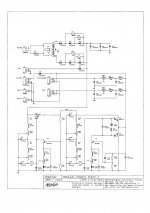
I attached full schematics of ISD player 5.4V main power supply. This power supply can run on both, mains power supply and external 12V battery.
Rectifier consists of a 3-stage stepped rectifier, conventional rectifiers, even Schottky, produce too much noise (peak charge current / back-emf) for these demanding applications.
T1 and T2 form a discrete 9V4 pre-regulator with a filtered LED reference (L1). T3, T4, and T5 form a discrete 5V4 post regulator with complementary output formed by Darlingtons T4 and T5. Bias is set with L3 and D9.
The filters in base circuit of T1 and T5 ensure clean base drive voltage.
Power supply dynamic response is fine-tuned with C17, C18 and C19. In order to achieve lowest possible grain, no constant current sources nor current mirrors could be used. The short feedback path ensures fast response. Transistors T2 and T3 are selected for low noise.
5V4 output voltage then passes 4th order LC filters that further reduce noise and interference levels.
This very low noise output voltage is still too noisy for the 4-crystal superclock.
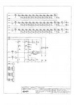
I added a second schematic diagram showing the TDA1543 DAC module, used in the ISD player (TDA1541A DAC module is currently being developed).
Upper 20th order LC lowpass power supply filter / current limiter (FB1 ... FB2) feeds the 4-crystal superclock and limits current (choke DC resistance). The 4-crystal superclock uses 2 filtered LED shunt regulators that provide +2v and -2V with respect to the reference voltage.
next two 20th order LC filters provide both L and R channel reference voltages (VRL / VRR). I used filtered LEDs as shunt stabilizer.
Circuit also shows I2S attenuators for WS and DATA, BCK uses a DJA circuit.
4-crystal superclock is indicated as U2 (4XO).
At these levels there is little to measure, when using this power supply, perceived sound quality is highly transparent, sparkling and refined. Voices are completely free of "edge". Some people who listened to the latest ISD player had difficulties hearing any difference between mains and battery operation.
You're complementary output powersupply -part (Module-Power Supply, of 16-01-2010) interests me. (had thoughts in this direction for years)
Can you tell us some more about it?
You mentioned that shunt-regulator would be limited...(I wanted to implement Sales or Ikflexer's Shunt)
I attached full schematics of ISD player 5.4V main power supply. This power supply can run on both, mains power supply and external 12V battery.
Rectifier consists of a 3-stage stepped rectifier, conventional rectifiers, even Schottky, produce too much noise (peak charge current / back-emf) for these demanding applications.
T1 and T2 form a discrete 9V4 pre-regulator with a filtered LED reference (L1). T3, T4, and T5 form a discrete 5V4 post regulator with complementary output formed by Darlingtons T4 and T5. Bias is set with L3 and D9.
The filters in base circuit of T1 and T5 ensure clean base drive voltage.
Power supply dynamic response is fine-tuned with C17, C18 and C19. In order to achieve lowest possible grain, no constant current sources nor current mirrors could be used. The short feedback path ensures fast response. Transistors T2 and T3 are selected for low noise.
5V4 output voltage then passes 4th order LC filters that further reduce noise and interference levels.
This very low noise output voltage is still too noisy for the 4-crystal superclock.
I added a second schematic diagram showing the TDA1543 DAC module, used in the ISD player (TDA1541A DAC module is currently being developed).
Upper 20th order LC lowpass power supply filter / current limiter (FB1 ... FB2) feeds the 4-crystal superclock and limits current (choke DC resistance). The 4-crystal superclock uses 2 filtered LED shunt regulators that provide +2v and -2V with respect to the reference voltage.
next two 20th order LC filters provide both L and R channel reference voltages (VRL / VRR). I used filtered LEDs as shunt stabilizer.
Circuit also shows I2S attenuators for WS and DATA, BCK uses a DJA circuit.
4-crystal superclock is indicated as U2 (4XO).
How does it perform?
At these levels there is little to measure, when using this power supply, perceived sound quality is highly transparent, sparkling and refined. Voices are completely free of "edge". Some people who listened to the latest ISD player had difficulties hearing any difference between mains and battery operation.
Attachments
Hi jameshillj,
The stepped rectifiers solved the problem at much lower cost. Problems with charge transfer supplies are increased switching noise (peak charge currents), and increased ripple voltage.
The stepped rectifiers greatly reduce switching noise as they switch-on and off in stages. Single rectifier goes into full conduction after transformer voltage exceeds reservoir cap voltage plus diode voltage drop, and switches-off immediately (risk of back emf and oscillations) when transformer voltage drops below reservoir cap voltage plus diode voltage drop.
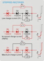
3-stage stepped rectifier starts with low charge current (series resistor #1, one diode conducts, step1), then increases charge current (series resistor #2, two diodes conduct, step 2), finally it provides full charge current (3 diodes conduct, step 3). Switching-off goes in reverse order, reduced charge current (2 diodes conduct, one is switched-off, step #2), lowest charge current (one diode conducts, two diodes are switched off, step #1), then it switches-off completely.
I use diode threshold voltage in combination with bypass resistors to achieve this (resistor already provides charge current when the diode is not yet conducting). One diode is not bypassed with a resistor, making sure current cannot flow in reverse direction.
I see that the Charge Transfer technique has not been included - is the performance unsatisfactory?
The stepped rectifiers solved the problem at much lower cost. Problems with charge transfer supplies are increased switching noise (peak charge currents), and increased ripple voltage.
The stepped rectifiers greatly reduce switching noise as they switch-on and off in stages. Single rectifier goes into full conduction after transformer voltage exceeds reservoir cap voltage plus diode voltage drop, and switches-off immediately (risk of back emf and oscillations) when transformer voltage drops below reservoir cap voltage plus diode voltage drop.
3-stage stepped rectifier starts with low charge current (series resistor #1, one diode conducts, step1), then increases charge current (series resistor #2, two diodes conduct, step 2), finally it provides full charge current (3 diodes conduct, step 3). Switching-off goes in reverse order, reduced charge current (2 diodes conduct, one is switched-off, step #2), lowest charge current (one diode conducts, two diodes are switched off, step #1), then it switches-off completely.
I use diode threshold voltage in combination with bypass resistors to achieve this (resistor already provides charge current when the diode is not yet conducting). One diode is not bypassed with a resistor, making sure current cannot flow in reverse direction.
Power supply dynamic response is fine-tuned with C17, C18 and C19. In order to achieve lowest possible grain, no constant current sources nor current mirrors could be used. The short feedback path ensures fast response. Transistors T2 and T3 are selected for low noise.
Hi John,
Thanks for your quick reply!
I coud find C19, but I don't see C17 en C18???
Interesting that you say that Current sources give grainy sound.
T3, T4, and T5 form a discrete 5V4 post regulator with complementary output formed by Darlingtons T4 and T5. Bias is set with L3 and D9.
Would this also be usable to supply a power amplifier? T5 is not really completely used as shunt is it? (powerloss/heat)
Same question came up by me.I see that the Charge Transfer technique has not been included - is the performance unsatisfactory?
With the Charge Transfer you wanted to keep out the High Frequency noise from the powernet,I thought. How does your stepped rectifier do this? (other then making the frequency pass higher by making the capacitance smaller by putting 3 diodes behind each other? Or is the way you choose by just heavily filtering with the inductors?
I have made the Charge transfer, by the way, and it seems to work properly (for Buffalo). But I agree that when it can be done simpler and cheaper that's the way to go.
By the way, could you tell us which inductors you use? (saves me an investigation through many types)
I also saw that you mentioned that the stepped rectifier of your power amp has 5 diodes? Seems a strange number?
I added a second schematic diagram showing the TDA1543 DAC module, used in the ISD player (TDA1541A DAC module is currently being developed).
Yes, I also follow the other thread. Unfortunately it's getting polluted at the moment by discussions I don't think is really adding anything.... What I like about you're threads is that you give so much information and it's really adventures trying to follow you're seeking.
If you're TDA1541A module is ready I will buy one (and the clock), I am most curious of what you can get out of it. (I have the Buffalo, nice but I think there still a lot more to win)
Hi Overm,
I attached full schematics of ISD player 5.4V main power supply. This power supply can run on both, mains power supply and external 12V battery.
Rectifier consists of a 3-stage stepped rectifier, conventional rectifiers, even Schottky, produce too much noise (peak charge current / back-emf) for these demanding applications.
Very nice work, thank you for sharing!
I don't understand you use those EMI T-filter networks (ferrite/cap/ferrite), without connecting the cap-connection.. any particular reason?
I'm very sure you looked at pro's en contra and that your current rectification gives you the least noise, I'm just searching to understand: concerning the capacitive coupling from the mains-transformer (you mentioned before), having a direct connection from your transformer to GND is not reducing this effect towards the audio circuit. Did you do tests with an additional isolation transformer? Would a full wave rectifier and regulation on both poles (plus and GND as in your floating charge power supply) not reduce that coupling?
For low power consumption power supplies, I always use a resistor of a couple of Ohms in series with every diode and 10nF ceramic cap directly parallel with the diode since I ones saw something like that in a power supply of the preamp from Elector in the past. It made sence and doing it since. Your progressive switching might be more efficient, but you believe it to be less noisy?
Thank you for your comments,
Thanks John, for reply post #429 - so simple.
I noticed Overm's comment about the use of 5 series diodes for your amplifier - would it be possible to see the resistor ratios for use with diodes like the Phillips BYW29 (or BYW99) for example?
Looking forward to see how well the SD + '41A chip functions and sounds.
I noticed Overm's comment about the use of 5 series diodes for your amplifier - would it be possible to see the resistor ratios for use with diodes like the Phillips BYW29 (or BYW99) for example?
Looking forward to see how well the SD + '41A chip functions and sounds.
I coud find C19, but I don't see C17 en C18???
I found C18 it's 1nF, it looked in the picture like it was C10. And C17 found it in the stage before 22pF.
Hello everyone!
I have been following this thread for some time now, and it is exactly what I was looking for. Many thanks to John for his marvelous job, his share and patience.
I do have a question. Does a Wolfson Dac (Wm8741 from Twistedpair) would work on the I2s path out? And what about the clock frequency needed for the WM8741, can it be fed with your internal clock?
Sorry for my English, I havent practise a lot lately....
Thank you very much for your kind answers.
Jacques
Hi jack4474,
The SD-transport outputs I2S, 44.1/16, 32 bits/frame, this is supported by the WM8741.
The SD-transport has no internal clock, it requires an external 11.2896 MHz low jitter clock (slaved clock operation).
I do have a question. Does a Wolfson Dac (WM8741 from Twistedpair) would work on the I2s path out?
The SD-transport outputs I2S, 44.1/16, 32 bits/frame, this is supported by the WM8741.
for the WM8741, can it be fed with your internal clock?
The SD-transport has no internal clock, it requires an external 11.2896 MHz low jitter clock (slaved clock operation).
Hi 2A3SET,
MURATA|DSS6NZ82A103Q55B|CAPACITOR, 3 TERMINAL, 10000PF | Farnell Nederland
Can you give the model of ferrite bead you are using?
MURATA|DSS6NZ82A103Q55B|CAPACITOR, 3 TERMINAL, 10000PF | Farnell Nederland
Hi Overm,
I use diode threshold voltage for switching between 2 or more different charge currents. Using 3 Schottky diode in series requires approx. 3 x 0.4V = 1.2V drop before all diodes start conducting.
When secondary voltage exceeds 0.4V plus voltage across reservoir cap, only one diode can conduct. The charge current now flows through a resistor, bypassing the two diodes that cannot conduct yet. When voltage exceeds 0.8V plus voltage across reservoir cap, two diodes start conducting. Third diode can't conduct yet, so current flows through resistors. When secondary exceeds 1.2V plus voltage across reservoir cap, all 3 diodes conduct, bypassing all resistors, providing full charge current.
So what basically happens is that charge current is increased and decreased step-wise (stepped rectifier). This avoids peak charge currents and possible back emf / oscillations.
I also attached a diagram that shows charge current flow at each step.
It has 5 double rectifier diodes in TO-220 package (fast, slow recovery). I can only use 2 diodes in one package that have cathodes connected, I only use single diodes from the remaining 4 TO-220 rectifiers (6 diodes connected in total). I used a Graetz bridge with a 2-stage stepped rectifier in the plus only. I use 39R current limiting resistors.
I use Panasonic ferrite-core inductors.
How does your stepped rectifier do this? (other then making the frequency pass higher by making the capacitance smaller by putting 3 diodes behind each other? Or is the way you choose by just heavily filtering with the inductors?
I use diode threshold voltage for switching between 2 or more different charge currents. Using 3 Schottky diode in series requires approx. 3 x 0.4V = 1.2V drop before all diodes start conducting.
When secondary voltage exceeds 0.4V plus voltage across reservoir cap, only one diode can conduct. The charge current now flows through a resistor, bypassing the two diodes that cannot conduct yet. When voltage exceeds 0.8V plus voltage across reservoir cap, two diodes start conducting. Third diode can't conduct yet, so current flows through resistors. When secondary exceeds 1.2V plus voltage across reservoir cap, all 3 diodes conduct, bypassing all resistors, providing full charge current.
So what basically happens is that charge current is increased and decreased step-wise (stepped rectifier). This avoids peak charge currents and possible back emf / oscillations.
I also attached a diagram that shows charge current flow at each step.
I also saw that you mentioned that the stepped rectifier of your power amp has 5 diodes? Seems a strange number?
It has 5 double rectifier diodes in TO-220 package (fast, slow recovery). I can only use 2 diodes in one package that have cathodes connected, I only use single diodes from the remaining 4 TO-220 rectifiers (6 diodes connected in total). I used a Graetz bridge with a 2-stage stepped rectifier in the plus only. I use 39R current limiting resistors.
By the way, could you tell us which inductors you use? (saves me an investigation through many types)
I use Panasonic ferrite-core inductors.
Attachments
Hi Berny,
I only use the double ferrite beads that are part of the LCL filter, so the filters could be replaced by suitable ferrite beads. The reason I put both a choke and a ferrite bead in series is to maintain high impedance at higher frequencies.
This is only problematic when the interference creates a ground loop. The ISD player has one central star ground for all audio components (SD-transport, DAC, volume control, power amps), eliminating ground loop issues. For purists, the entire SD-player can be powered off-line using 3 x 12V battery (36V for the bridge power amps and a tap at 12V for the logic power supply). This is about as clean as it gets. The entire ISD player (power amps inclusive) consumes approx. 20 watts, so suitable batteries can last long enough.
It's already very difficult to hear any difference at all, between a floating battery power supply and a heavily polluted mains power supply (I live near an industrial area).
The series resistor often causes laid-back sound, same applies for mains filters. The 10nF bypass cap also passes RF/HF mains interference (short-circuits diode for RF / HF). I use Schottky diodes, these don't require bypass caps.
It was the only way to achieve required low noise levels in the ISD player when running on mains power.
The circuit is cheap and simple, why not just try it, and compare it with a conventional rectifier. When using a switch to bypass the stepped rectifier diodes, you can toggle between conventional and stepped rectifiers while listening.
I don't understand you use those EMI T-filter networks (ferrite/cap/ferrite), without connecting the cap-connection.. any particular reason?
I only use the double ferrite beads that are part of the LCL filter, so the filters could be replaced by suitable ferrite beads. The reason I put both a choke and a ferrite bead in series is to maintain high impedance at higher frequencies.
concerning the capacitive coupling from the mains-transformer (you mentioned before), having a direct connection from your transformer to GND is not reducing this effect towards the audio circuit.
This is only problematic when the interference creates a ground loop. The ISD player has one central star ground for all audio components (SD-transport, DAC, volume control, power amps), eliminating ground loop issues. For purists, the entire SD-player can be powered off-line using 3 x 12V battery (36V for the bridge power amps and a tap at 12V for the logic power supply). This is about as clean as it gets. The entire ISD player (power amps inclusive) consumes approx. 20 watts, so suitable batteries can last long enough.
Did you do tests with an additional isolation transformer? Would a full wave rectifier and regulation on both poles (plus and GND as in your floating charge power supply) not reduce that coupling?
It's already very difficult to hear any difference at all, between a floating battery power supply and a heavily polluted mains power supply (I live near an industrial area).
For low power consumption power supplies, I always use a resistor of a couple of Ohms in series with every diode and 10nF ceramic cap directly parallel with the diode since I ones saw something like that in a power supply of the preamp from Elector in the past. It made sence and doing it since. Your progressive switching might be more efficient, but you believe it to be less noisy?
The series resistor often causes laid-back sound, same applies for mains filters. The 10nF bypass cap also passes RF/HF mains interference (short-circuits diode for RF / HF). I use Schottky diodes, these don't require bypass caps.
Your progressive switching might be more efficient, but you believe it to be less noisy?
It was the only way to achieve required low noise levels in the ISD player when running on mains power.
The circuit is cheap and simple, why not just try it, and compare it with a conventional rectifier. When using a switch to bypass the stepped rectifier diodes, you can toggle between conventional and stepped rectifiers while listening.
- Status
- This old topic is closed. If you want to reopen this topic, contact a moderator using the "Report Post" button.
- Home
- Source & Line
- Digital Source
- Lossless SD-card player