Hi John.
1.
The missing sub output I'd consider a pretty weak point. Though, it's not really missing, what's missing is a solution from you about the subject.
Quite some people are running subs and would like to hook up an active crossover in parallel. Some are using output transformers with a 2nd secondary. Or even a 2nd DAC module could be used ( DDDAC) .
Of course this is not perfect, however it works pretty well - I consider it a good compromise. By playing with phase and timing on the crossover, you'll get a pretty decent solution.
For a perfect solution we would need active filtered multichannels of course - we are aware of it.
An interesting solution in your setup could be also a second DAC board with an output transformer to decouple from the active stage of the crossover and the primary DAC. This you can do e.g. with a DDDAC24 - you use the first module for the mids/highs the second module for the woofer.
As you know -- I am well aware that any new feature will compromise your current design. Though as we all know at a certain stage you have to go for a compromise.
And if you ask me - I'll never run without subs. And we all know that you love to be challenged!")
2. I also don't understand your POT solution. And your explanation I don't understand either. Are you telling us that since the source is that great you ( or we) can live with a compromise on the POT side? In my setups the sound of Alps pot reminded me always at towels in front of my speakers (compared to several other solutions)
As discussed earlier - the only solution I see is a switchable voltage divider on the DAC output. Only this solution won't add another part ( except the switch/relay) to the setup.
Cheers
\Klaus
1.
The missing sub output I'd consider a pretty weak point. Though, it's not really missing, what's missing is a solution from you about the subject.
Quite some people are running subs and would like to hook up an active crossover in parallel. Some are using output transformers with a 2nd secondary. Or even a 2nd DAC module could be used ( DDDAC) .
Of course this is not perfect, however it works pretty well - I consider it a good compromise. By playing with phase and timing on the crossover, you'll get a pretty decent solution.
For a perfect solution we would need active filtered multichannels of course - we are aware of it.
An interesting solution in your setup could be also a second DAC board with an output transformer to decouple from the active stage of the crossover and the primary DAC. This you can do e.g. with a DDDAC24 - you use the first module for the mids/highs the second module for the woofer.
As you know -- I am well aware that any new feature will compromise your current design. Though as we all know at a certain stage you have to go for a compromise.
And if you ask me - I'll never run without subs. And we all know that you love to be challenged!
2. I also don't understand your POT solution. And your explanation I don't understand either. Are you telling us that since the source is that great you ( or we) can live with a compromise on the POT side? In my setups the sound of Alps pot reminded me always at towels in front of my speakers (compared to several other solutions)
As discussed earlier - the only solution I see is a switchable voltage divider on the DAC output. Only this solution won't add another part ( except the switch/relay) to the setup.
Cheers
\Klaus
I also don't understand your POT solution. And your explanation I don't understand either. Are you telling us that since the source is that great you ( or we) can live with a compromise on the POT side? In my setups the sound of Alps pot reminded me always at towels in front of my speakers (compared to several other solutions)
ALPS pots have a good reputation and should do well for a 1543 DAC.
My only concern in this app would be channel inbalance at low volume settings.
Perhaps blue or black ALPS with tighter specs should be used here.
ALPS pots have a good reputation and should do well for a 1543 DAC.
My only concern in this app would be channel inbalance at low volume settings.
Perhaps blue or black ALPS with tighter specs should be used here.
You know - we can't talk of handwired output I/V reference resistors making an excellent job on one side and at the same time we're talking about a pretty poor "divider" in front of the amp, which is supposed to be "good enough". Somebody needs to explain what I am missing here.
BTW: Did John ever mention how he is running that pot? Perhaps it is not even sitting in the signalpath!?!?
I agree soundcheck - this just doesn't gel with the great efforts expended in other parts of the system!
About pots, when one knows the range of R that one uses normally with one's speakers (and in my case the lower and the higher volume are only 6db apart) one can parallel to the pot a suitable audiophile (even honeycomb) resistor to achieve greater clarity...at least this is the solution I found better...
Hi all,
I bought the DAC module with Superclock from John. I Think i am one of the first customers who got it Here's a little review.
As initial tryout i use (less expensive) Rhopoint I/V resistors instead of the handwired I/V resistors. As source i use a fully tweaked Squeezebox reciever (SBR) (running at 1.2V&3.3V) The Superclock feeds the SBR Xilinx processor with 11.289mhz. The I2S data from the Xilinx processor feeds the DAC. The amp i use the Lifeforce 100 from Aspen Amplifiers.
The past years I'll tried all kind of NOS and OS DAC's. While NOS DAC's have greater musicality they often lack some level of detail. John's approach to get the very best out of a TDA1534 looked very special and uncommon to me. It was a reason to buy and try this DAC.
I was gladly surprised by the sound. Never thought that other good TDA154x DAC's like DDDac and Monica could be beaten; i mean, what can be done better with simple 8 pin DAC chip??
All the 'rare and uncommon' method's of John's approach makes that this DAC sounds like i ever wanted that a DAC sounds like. It's musical, brilliant, lively and not to forget has more/better resolution. For listening fun it beats every DAC i ever had or heard. Even the Buffalo's and Wolfson's. It breaths music and has heavenly mid-attacks. Piano's and drum's roll's out of the speakers as they are playing behind the curtain. Remarkable is that this 'feel' got complete after connecting 3u3 Monacor MKT coupling cap's from 3 euro piece! John told me that this coupling cap is the (only?) right choice for this application.
At the moment very happy with it. It could be my last DAC for 44.1 source material. Thanks John.
I bought the DAC module with Superclock from John. I Think i am one of the first customers who got it
Here's a little review.As initial tryout i use (less expensive) Rhopoint I/V resistors instead of the handwired I/V resistors. As source i use a fully tweaked Squeezebox reciever (SBR) (running at 1.2V&3.3V) The Superclock feeds the SBR Xilinx processor with 11.289mhz. The I2S data from the Xilinx processor feeds the DAC. The amp i use the Lifeforce 100 from Aspen Amplifiers.
The past years I'll tried all kind of NOS and OS DAC's. While NOS DAC's have greater musicality they often lack some level of detail. John's approach to get the very best out of a TDA1534 looked very special and uncommon to me. It was a reason to buy and try this DAC.
I was gladly surprised by the sound. Never thought that other good TDA154x DAC's like DDDac and Monica could be beaten; i mean, what can be done better with simple 8 pin DAC chip??
All the 'rare and uncommon' method's of John's approach makes that this DAC sounds like i ever wanted that a DAC sounds like. It's musical, brilliant, lively and not to forget has more/better resolution. For listening fun it beats every DAC i ever had or heard. Even the Buffalo's and Wolfson's. It breaths music and has heavenly mid-attacks. Piano's and drum's roll's out of the speakers as they are playing behind the curtain. Remarkable is that this 'feel' got complete after connecting 3u3 Monacor MKT coupling cap's from 3 euro piece! John told me that this coupling cap is the (only?) right choice for this application.
At the moment very happy with it. It could be my last DAC for 44.1 source material. Thanks John.
Thanks Bertel, can you say anything about the difference between using this clock back to the Squeezebox versus running the squeezebox with on-board 11.289MHz crystal?
Are you replying on Brubeck? Then it's Hans ;-) (Hybride) Forgot my password once so had to choose another nickname here.
About your question. Difficult to answer. Effect depends on the DAC i think. As you know i had good results with the Tentlab clock, so a good clock matters. With this DAC i can't do a A/B because the DAC needs a slaved source to work (necessary for re-clocking the BCK)
Sorry Hans, mixing myself up from the other placeAre you replying on Brubeck? Then it's Hans ;-) (Hybride) Forgot my password once so had to choose another nickname here.
OK, so no night & day difference!About your question. Difficult to answer. Effect depends on the DAC i think. As you know i had good results with the Tentlab clock, so a good clock matters. With this DAC i can't do a A/B because the DAC needs a slaved source to work (necessary for re-clocking the BCK)
Hi jkeny,
The way the master clock is used makes all the difference, I tried to connect fewest possible clock loads and tried to isolate clock loads, preventing crosstalk between loads.
In most common designs, the synchronous reclocker or divider is external, connected through (a few inches) of wire. In these ultra low jitter applications, every millimeter of interconnection counts. The longer the interconnections, the higher the risk of picking-up unwanted interference that not relates to the master clock jitter spectrum, significantly increasing jitter.
One of the special features of the 4-crystal master clock is that the single synchronous reclocker is merged into the master clock, ensuring shortest possible link between master clock output and synchronous reclocker input, thus reducing unwanted interference to an absolute minimum. In order to prevent negative effects from higher harmonics, the masterclock output signal is filtered (fundamental) prior to feeding it to the integrated reclocker. In order to prevent possible timing uncertainty, both reclocker and master clock power supplies and reference voltages track.
In order to completely isolate the highly sensitive synchronous reclocker circuit from the main (buffered) master clock output (that might pick-up interference from connected clock loads), the synchronous reclocker is driven through a capacitive node (<1pF).
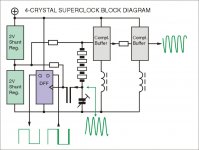
I attached 4-crystal master clock block diagram, this is the master clock integrated in the TDA1543 DAC module.
Two filtered LED shunt regs create plus and minus 2V with respect to the reference voltage. The shunt regs are powered by a 20th order LC filter, located on the TDA1543 PCB. This LC filter also provides required current limiting (choke DC resistance).
The oscillator is built around a complementary choke-loaded JFET buffer. This type of buffer provided highest PSRR by far. Frequency is set by 4 crystals that are placed in series, these also filter the oscillator signal (output across 2.5pF PTFE trimmer). The filtered output signal is the fundamental (sine wave) with high spectral purity. Amplitude is much higher than the 4V power supply (calculated 20Vpp). I can't measure exact amplitude as the scope probe forms a capacitive load (>10pF) that significantly reduces amplitude during measuring. The probe also significantly increases jitter by injecting noise (ground loops, mains powered measuring equipment).
Reference voltage is applied through a bulk metal foil 100K resistor (other resistors were too noisy). The oscillator has total of 9 components, 4 crystals, 2 JFETs, one PTFE trimmer, one bulk metal foil resistor, and one choke. Frequency can be set to exact value (11.2896 MHz) using the PTFE trimmer.
Output buffer (2 JFETs, one choke and one resistor) drives the source (SD-transport, CD transport or squeezebox for example).
The I2S timing signal of interest for the TDA154x series is BCK. So the BCK output of the source is synchronously reclocked, but if required the word clock can be reclocked instead. The synchronous reclocker will have big impact on final jitter levels / spectrum, and is the heart of the timing system.
I tested PECL, ECL and high speed CMOS flip-flops. Both PECL and ECL consumed much more power and produced a lot more interference, including power supply pollution. The high speed CMOS (180 MHz), with special clock injection (using a bias voltage) provided best (audible) results. The D fip-flop is clocked with 11.2896 MHz and reclocks 1.4112 MHz.
The TDA1543 runs on lowest possible bit clock (44.1/16) of 1.4112 MHz, this greatly reduces on-chip ground-bounce. ground bounce increases with both, increasing frequency and increasing voltage.
Alternative to synchronous reclocking would be using a divider to extract 1.4112 MHz, but since this divider requires multiple D flip-flops, its likely to produce higher jitter compared to a single flip-flop used in a synchronous reclocker.
In order to feed cleanest possible clock signal to the reclocker, the filtered output signal of the crystal oscillator (across the trimmer) is fed to the reclocker using a capacitive node and using shortest possible connection. That's why it has to be integrated in the superclock module. The reclocker clock input is set at exactly the same reference level as the crystal oscillator, using a resistor. This way, both crystal oscillator and reclocker "track", so minor power supply fluctuations are common for both circuits, reducing trigger uncertainty.
The reclockerd output signal is then only fed to the DAC chip using a dynamic jitter attenuator, that basically compensates for TDA1543 on-chip jitter (ground-bounce) by providing pre-compensation. It basically counter-acts the effects of on-chip ground-bounce caused by the BCK signal. The DJA circuit has to be carefully tuned with a given DAC chip in order to achieve best pre-compensation. Different type of DAC chip (TDA1541A for example) requires re-tuning.
This master clock approach enables something that's very difficult to achieve with conventional designs, extreme low sample timing jitter at the OUTPUT of the DAC chip where it matters most.
Ultra low jitter masterclock is basically useless if resulting sample timing jitter at the DAC output is still high, due to on-chip ground-bounce. It's very likely that modern DAC chips like the Sabre DAC for example (using very high on-chip frequencies) suffer more form increased sample timing jitter at the DAC output, as a result of increased on-chip ground-bounce.
The way the master clock is used makes all the difference, I tried to connect fewest possible clock loads and tried to isolate clock loads, preventing crosstalk between loads.
In most common designs, the synchronous reclocker or divider is external, connected through (a few inches) of wire. In these ultra low jitter applications, every millimeter of interconnection counts. The longer the interconnections, the higher the risk of picking-up unwanted interference that not relates to the master clock jitter spectrum, significantly increasing jitter.
One of the special features of the 4-crystal master clock is that the single synchronous reclocker is merged into the master clock, ensuring shortest possible link between master clock output and synchronous reclocker input, thus reducing unwanted interference to an absolute minimum. In order to prevent negative effects from higher harmonics, the masterclock output signal is filtered (fundamental) prior to feeding it to the integrated reclocker. In order to prevent possible timing uncertainty, both reclocker and master clock power supplies and reference voltages track.
In order to completely isolate the highly sensitive synchronous reclocker circuit from the main (buffered) master clock output (that might pick-up interference from connected clock loads), the synchronous reclocker is driven through a capacitive node (<1pF).
I attached 4-crystal master clock block diagram, this is the master clock integrated in the TDA1543 DAC module.
Two filtered LED shunt regs create plus and minus 2V with respect to the reference voltage. The shunt regs are powered by a 20th order LC filter, located on the TDA1543 PCB. This LC filter also provides required current limiting (choke DC resistance).
The oscillator is built around a complementary choke-loaded JFET buffer. This type of buffer provided highest PSRR by far. Frequency is set by 4 crystals that are placed in series, these also filter the oscillator signal (output across 2.5pF PTFE trimmer). The filtered output signal is the fundamental (sine wave) with high spectral purity. Amplitude is much higher than the 4V power supply (calculated 20Vpp). I can't measure exact amplitude as the scope probe forms a capacitive load (>10pF) that significantly reduces amplitude during measuring. The probe also significantly increases jitter by injecting noise (ground loops, mains powered measuring equipment).
Reference voltage is applied through a bulk metal foil 100K resistor (other resistors were too noisy). The oscillator has total of 9 components, 4 crystals, 2 JFETs, one PTFE trimmer, one bulk metal foil resistor, and one choke. Frequency can be set to exact value (11.2896 MHz) using the PTFE trimmer.
Output buffer (2 JFETs, one choke and one resistor) drives the source (SD-transport, CD transport or squeezebox for example).
The I2S timing signal of interest for the TDA154x series is BCK. So the BCK output of the source is synchronously reclocked, but if required the word clock can be reclocked instead. The synchronous reclocker will have big impact on final jitter levels / spectrum, and is the heart of the timing system.
I tested PECL, ECL and high speed CMOS flip-flops. Both PECL and ECL consumed much more power and produced a lot more interference, including power supply pollution. The high speed CMOS (180 MHz), with special clock injection (using a bias voltage) provided best (audible) results. The D fip-flop is clocked with 11.2896 MHz and reclocks 1.4112 MHz.
The TDA1543 runs on lowest possible bit clock (44.1/16) of 1.4112 MHz, this greatly reduces on-chip ground-bounce. ground bounce increases with both, increasing frequency and increasing voltage.
Alternative to synchronous reclocking would be using a divider to extract 1.4112 MHz, but since this divider requires multiple D flip-flops, its likely to produce higher jitter compared to a single flip-flop used in a synchronous reclocker.
In order to feed cleanest possible clock signal to the reclocker, the filtered output signal of the crystal oscillator (across the trimmer) is fed to the reclocker using a capacitive node and using shortest possible connection. That's why it has to be integrated in the superclock module. The reclocker clock input is set at exactly the same reference level as the crystal oscillator, using a resistor. This way, both crystal oscillator and reclocker "track", so minor power supply fluctuations are common for both circuits, reducing trigger uncertainty.
The reclockerd output signal is then only fed to the DAC chip using a dynamic jitter attenuator, that basically compensates for TDA1543 on-chip jitter (ground-bounce) by providing pre-compensation. It basically counter-acts the effects of on-chip ground-bounce caused by the BCK signal. The DJA circuit has to be carefully tuned with a given DAC chip in order to achieve best pre-compensation. Different type of DAC chip (TDA1541A for example) requires re-tuning.
This master clock approach enables something that's very difficult to achieve with conventional designs, extreme low sample timing jitter at the OUTPUT of the DAC chip where it matters most.
Ultra low jitter masterclock is basically useless if resulting sample timing jitter at the DAC output is still high, due to on-chip ground-bounce. It's very likely that modern DAC chips like the Sabre DAC for example (using very high on-chip frequencies) suffer more form increased sample timing jitter at the DAC output, as a result of increased on-chip ground-bounce.
Attachments
OK, so no night & day difference!
I am wondering if "night and day difference" is really the point here.
If talking SBR we still talk about a pretty noisy environment.
You need to consider that the SBR will still introduce interferences/distortions.
This I consider the actual bottleneck. At that point it won't make a
difference if your clock delivers 40ps or 4ps jitter if the entire system allows for not more
then 200ps. Which might still be better then the stock 2000ps. ( all values are taken out of the air)
Each architecture has its limits.
To get around that you probably have to jump on the SD-card train.
I understand the parameters (at least I have the same premise as you - reduce the number of areas of interference to a minimum, John has done) & some of the reason behind asking that question was to evaluate whether the clock had an appreciable effect & if it was the underlying SB platform or the clock that was the bottleneck. I know the mods that brubeck has already applied & I've seen others report(maybe it was Hans?) that a Tent clock made no difference to the sound but there may have been other reasons for this i.e. using a Sabre DAC which has it's own re-clcoking (unless turned off via registers settings).I am wondering if "night and day difference" is really the point here.
If talking SBR we still talk about a pretty noisy environment.
You need to consider that the SBR will still introduce interferences/distortions.
This I consider the actual bottleneck. At that point it won't make a
difference if your clock delivers 40ps or 4ps jitter if the entire system allows for not more
then 200ps. Which might still be better then the stock 2000ps. ( all values are taken out of the air)
Each architecture has its limits.
To get around that you probably have to jump on the SD-card train.
I have experience of low-jitter & the night & day difference it makes to sound with my reference, a modded HiFace USB transport (I know USB has it's own limitations & bottlenecks
). This is a very noticeable, unmistakeable difference in SQ between before & after - it doesn't require A/B switching to pick it up! This is probably to do with the compact layout, minimum components & direct clock implementation (plus low-jitter clocks)So, I wasn't criticising John's design & thank him for his, as usual, very forthcoming explanation in which he addresses all that we mention above.
Hi John,
I have been following your threads for quite a while now and I must say you do extraordinary things. My biggest respect.
I have a first question: You use the TDA1543 (THD -75db) now, is the TDA1545 (THD -88db) also possible? The latter seems to have a bit better specs, has same connections (drop in replacement) still using current sources but featuring the continues calibration?
So, I wasn't criticising John's design & thank him for his, as usual, very forthcoming explanation in which he addresses all that we mention above.
Why not? John needs that feedback. If somebody is saying that the clock won't seem to make an audible difference in a certain environment, it is more then fair to tell him.
I am wondering if Hans has tested
1. his own DAC (1543/Wolfson) with either clock on the same powersupply
2. Johns DAC on either clock on the same powersupply
to have a somewhat valid test environment.
What Hans is not able to do anymore, is to hook up a Buffalo under the same conditions.
Hans: Did you hook-up the DAC before or after the damping resistors? Afaik the 22R resistors are not needed anymore with Johns DAC. ( Correct me if I'm wrong)
Cheers
Last edited:
I tested PECL, ECL and high speed CMOS flip-flops. Both PECL and ECL consumed much more power and produced a lot more interference, including power supply pollution. The high speed CMOS (180 MHz), with special clock injection (using a bias voltage) provided best (audible) results.
Quite the opposite is true.
Despite faster rise times, ECL has much less swing and produces less EMI, even more in differential designs.
It also produces much less supply noise because of internal differential & spike free design.
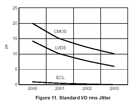
Most important, ECL flipflops range from 1 GHz to 4 GHz and have the lowest available jitter down to 200 fs. So I won't consider 180 MHz as "high speed".
Comparison of jitter performance between different logic families from ONsemi appl. note:
By the way, it is really astonishing... I remember when you was teaching us that all is lost when using volume attenuators before the power amp. "Loss of resolution" in the power amp was the key word. All forgotten, now you can not even hear a difference between a "pot" and far superior switched resistors or whatever better alternative. Maybe the system isn't good enough to reveal the differences ? Sorry, bad thought, but that comes to mind.
Ultra low jitter masterclock is basically useless if resulting sample timing jitter at the DAC output is still high, due to on-chip ground-bounce. It's very likely that modern DAC chips like the Sabre DAC for example (using very high on-chip frequencies) suffer more form increased sample timing jitter at the DAC output, as a result of increased on-chip ground-bounce.
You should maybe first prove the performance of your own system.
I personally have my doubts.
You never show any measurements.
Last but not least, this still is a DIY forum. Why not show the schematic of your clock ? Would be interesting for discussion and for education of you readers.
I am wondering if Hans has tested
1. his own DAC (1543/Wolfson) with either clock on the same powersupply
2. Johns DAC on either clock on the same powersupply
to have a somewhat valid test environment.
Hans: Did you hook-up the DAC before or after the damping resistors? Afaik the 22R resistors are not needed anymore with Johns DAC. ( Correct me if I'm wrong)
I ripped the I2S data after the 22R's as usual. Don't know if they make sense anymore.
At the time i switched to the Tentclock in the SBR, i had a custom mini TDA1543-DAC connected straight to I2S. The difference was audible. Better separation, more precise, cleaner. Didn't switch with the Wolfson.
---------------------------------------------------------------------->>
John and others: is there support to start a new thread about this TDA1543 DAC module only? This thread seems to me more the place for discussing the complete SD-card player concept. In the DAC thread we can also discuss about other sources for this DAC.
Last edited:
Hi jkeny,
It's not just sample timing jitter or interference. Sound quality depends on how well all audio components function as a unity.
Logical starting point is providing cleanest possible digital audio source. This means both, a source that offers lowest possible interference (noise) on both, power supplies and I2S outputs, and causes minimum pollution of the clock that drives it.
This is only the source, it needs to be clocked, and this in turn will determine how low the jitter on the I2S output will be. So both source and clock must form a unity.
The source outputs I2S, these signals still contain jitter that must be reduced. One of the advantages of the SD-transport is that it can be slaved. This means that the generated I2S signals can be easily reclocked synchronously.
Next problem, the more clock loads, the more likely that jitter increases. When reclocking the I2S DATA signal one risks crosstalk with the master clock, since the DATA signal changes randomly, this will cause unwanted jitter spectrum in the event of crosstalk.
It's easiest to minimize the amount of clock loads. So it's advisable to only synchronously reclock the timing signal of interest for the DAC that's going to be used. This must be done using the cleanest clock imaginable, using a clock buffer or comparator would add some extra jitter. That's why I used the filtered unbuffered sine wave output of the master clock for synchronous reclocking. This in turn demands integration of synchronous reclocker and master clock.
Now we finally have a clean digital audio source, and a low jitter timing signal (I use BCK) for the DAC chip.
Next problem, I2S signals switch rapidly, generating higher harmonics. Simply connecting these signals to the DAC, even when using impedance matching, would dump these unwanted harmonics on the DAC chip circuit and would end up (intermodulates) with the generated analogue output signal.
Therefore it's important to minimize the effects of I2S crosstalk. This can be done using I2S attenuators. I attenuate all I2S signals to approx.200mVpp before feeding them to the DAC chip.
The DAC chip is the next problem. On the chip we have a large number of semiconductors that switch with the I2S and optional system clock signals. This causes on-chip ground-bounce. ground-bounce affects trigger uncertainty and therefore will cause on-chip jitter (despite low jitter input signals). This in turn will lead to increased sample timing jitter, not because of the master clock, but because of the on-chip ground-bounce.
Ground bounce increases with both voltage and frequency. In order to minimize on-chip ground bounce, both power supply voltage and highest on-chip clock frequency are best reduced to lowest possible values. This basically excludes all modern DAC chips that use on-chip frequency multipliers to drive the (nested) delta-sigma modulators. These use approx. 200 MHz on-chip, this is a similar technique as used in micro-processors where highest clock frequency has to be generated on-chip as the external circuits wouldn't be able to handle such high frequencies. It's common knowledge that when multiplying a clock frequency, say from 11.2896 MHz to say 191.923 MHz, jitter will likely increase (PLL).
So now we have to make compromises, either low sample timing jitter or high resolution, we can't have both.
This is why I use chips that can run on highest frequency of 1.4112 MHz, this ensures lowest possible on-chip ground-bounce and makes it easier to achieve low sample timing jitter. Since the TDA1543 architecture is so simple and straight forward, it's even possible to predict how ground-bounce will effect sample timing jitter, and provide pre-compensation in order to further limit the effects of on-chip ground-bounce (Dynamic Jitter Attenuator). This is not possible with modern chips because of highly increased complexity of the DAC chip circuits.
Next issue is digital filtering. One could discuss advantages of OS vs NOS, I simply listened to both options and chose the one that most closely matched live sound quality, in other words the one that produced most NATURAL sound.
That was the digital (timing) part.
Next the analogue part. Based on research and listening tests I know that it's easiest to achieve natural sound quality when using fewest (active) parts in the analogue signal path. This includes the analogue signal path in the DAC chip!
Modern DAC chips use on-chip switched capacitor filters. These consist of on-chip sample capacitors that temporarily hold an analogue voltage. This voltage has to be buffered, so an (OP-amp) buffer is added. Since switched-capacitor filters require multiple switches, multiple capacitor / buffer stages have to be cascaded. Depending on DAC chip architecture, a buffer / amplifier is also integrated in order to provide voltage output.
I use DAC chips that only use a constant current source, some passive current dividers (emitter scaling) and some bit switches, so no sampling caps, no buffers, just a direct constant current output. This is as basic as it gets, and this puts as few (active) components in the analogue signal path as possible.
Next problem, conversion. Sooner or later the output current of the DAC chip needs to be converted into a voltage. The most basic method that also places fewest (active) components in the signal path is a resistor. I used the best possible resistor for this task, but I had to construct it myself. What we need is a resistor with lowest possible noise (high wattage wire wound), non-inductive (mobius loop), low self capacitance (honeycomb winding structure), non-magnetic (selecting appropriate resistive wire), low TC (resistive wire with low TC), and fewest bi-metallic couplings like end caps fitted on a metal film resistor for example. I directly solder the resistive wire to the circuit, reducing the amount of bi-metallic couplings to a minimum.
It would be nice if the voltage across the I/V resistor could directly drive a power amp, this way, no extra parts have to be added to the signal path. The TDA1543 is one of very few DAC chips that offers this option.
Once the DAC output current is converted into a voltage, it's highly sensitive to external interference that would simply super-impose on this signal. Biggest interference source is caused by GND wiring and the (interference) signals that run through these. Therefore best GND wiring strategy is mandatory for achieving best performance.
Example with 16 bit resolution and 2Vpp output signal, LSB represents 2 / 2^16 = 30.5uV. This means that all external interference must stay well below30.5uV, something that's virtually impossible when using separate audio components, linked with RCA / XLR interlinks. Even worse, after attenuation, this LSB signal level could easily drop to 3.5uV, making matters even much worse. Now think of 24 bit resolution, corresponding to say 2 / 2^24 = 119 nano volts, this would drop to 11.9 nano volts after attenuation. This is why I don't bother about hi-res formats, as these extreme low level signals simply won't make it to the speaker.
This also shows why system noise and interference levels need to be exceptionally low in order to extract as much detail as possible. This includes super clean power supplies and no ground loops.
Next hurdle, the power amp. Suppose the low level detail makes it to the power amp input, then it can still be masked by power amp limited resolution, or by speaker / power amp inter-action.
All these issues are addressed, and systematically tackled in the ISD player, that's also why integration of audio components is an absolute necessity in order to get maximum resolution, and resulting most natural sound reproduction. This is also the easiest way to get all required audio components function as a unity.
I understand the parameters (at least I have the same premise as you - reduce the number of areas of interference to a minimum, John has done) & some of the reason behind asking that question was to evaluate whether the clock had an appreciable effect & if it was the underlying SB platform or the clock that was the bottleneck. I know the mods that brubeck has already applied & I've seen others report(maybe it was Hans?) that a Tent clock made no difference to the sound but there may have been other reasons for this i.e. using a Sabre DAC which has it's own re-clcoking (unless turned off via registers settings).
It's not just sample timing jitter or interference. Sound quality depends on how well all audio components function as a unity.
Logical starting point is providing cleanest possible digital audio source. This means both, a source that offers lowest possible interference (noise) on both, power supplies and I2S outputs, and causes minimum pollution of the clock that drives it.
This is only the source, it needs to be clocked, and this in turn will determine how low the jitter on the I2S output will be. So both source and clock must form a unity.
The source outputs I2S, these signals still contain jitter that must be reduced. One of the advantages of the SD-transport is that it can be slaved. This means that the generated I2S signals can be easily reclocked synchronously.
Next problem, the more clock loads, the more likely that jitter increases. When reclocking the I2S DATA signal one risks crosstalk with the master clock, since the DATA signal changes randomly, this will cause unwanted jitter spectrum in the event of crosstalk.
It's easiest to minimize the amount of clock loads. So it's advisable to only synchronously reclock the timing signal of interest for the DAC that's going to be used. This must be done using the cleanest clock imaginable, using a clock buffer or comparator would add some extra jitter. That's why I used the filtered unbuffered sine wave output of the master clock for synchronous reclocking. This in turn demands integration of synchronous reclocker and master clock.
Now we finally have a clean digital audio source, and a low jitter timing signal (I use BCK) for the DAC chip.
Next problem, I2S signals switch rapidly, generating higher harmonics. Simply connecting these signals to the DAC, even when using impedance matching, would dump these unwanted harmonics on the DAC chip circuit and would end up (intermodulates) with the generated analogue output signal.
Therefore it's important to minimize the effects of I2S crosstalk. This can be done using I2S attenuators. I attenuate all I2S signals to approx.200mVpp before feeding them to the DAC chip.
The DAC chip is the next problem. On the chip we have a large number of semiconductors that switch with the I2S and optional system clock signals. This causes on-chip ground-bounce. ground-bounce affects trigger uncertainty and therefore will cause on-chip jitter (despite low jitter input signals). This in turn will lead to increased sample timing jitter, not because of the master clock, but because of the on-chip ground-bounce.
Ground bounce increases with both voltage and frequency. In order to minimize on-chip ground bounce, both power supply voltage and highest on-chip clock frequency are best reduced to lowest possible values. This basically excludes all modern DAC chips that use on-chip frequency multipliers to drive the (nested) delta-sigma modulators. These use approx. 200 MHz on-chip, this is a similar technique as used in micro-processors where highest clock frequency has to be generated on-chip as the external circuits wouldn't be able to handle such high frequencies. It's common knowledge that when multiplying a clock frequency, say from 11.2896 MHz to say 191.923 MHz, jitter will likely increase (PLL).
So now we have to make compromises, either low sample timing jitter or high resolution, we can't have both.
This is why I use chips that can run on highest frequency of 1.4112 MHz, this ensures lowest possible on-chip ground-bounce and makes it easier to achieve low sample timing jitter. Since the TDA1543 architecture is so simple and straight forward, it's even possible to predict how ground-bounce will effect sample timing jitter, and provide pre-compensation in order to further limit the effects of on-chip ground-bounce (Dynamic Jitter Attenuator). This is not possible with modern chips because of highly increased complexity of the DAC chip circuits.
Next issue is digital filtering. One could discuss advantages of OS vs NOS, I simply listened to both options and chose the one that most closely matched live sound quality, in other words the one that produced most NATURAL sound.
That was the digital (timing) part.
Next the analogue part. Based on research and listening tests I know that it's easiest to achieve natural sound quality when using fewest (active) parts in the analogue signal path. This includes the analogue signal path in the DAC chip!
Modern DAC chips use on-chip switched capacitor filters. These consist of on-chip sample capacitors that temporarily hold an analogue voltage. This voltage has to be buffered, so an (OP-amp) buffer is added. Since switched-capacitor filters require multiple switches, multiple capacitor / buffer stages have to be cascaded. Depending on DAC chip architecture, a buffer / amplifier is also integrated in order to provide voltage output.
I use DAC chips that only use a constant current source, some passive current dividers (emitter scaling) and some bit switches, so no sampling caps, no buffers, just a direct constant current output. This is as basic as it gets, and this puts as few (active) components in the analogue signal path as possible.
Next problem, conversion. Sooner or later the output current of the DAC chip needs to be converted into a voltage. The most basic method that also places fewest (active) components in the signal path is a resistor. I used the best possible resistor for this task, but I had to construct it myself. What we need is a resistor with lowest possible noise (high wattage wire wound), non-inductive (mobius loop), low self capacitance (honeycomb winding structure), non-magnetic (selecting appropriate resistive wire), low TC (resistive wire with low TC), and fewest bi-metallic couplings like end caps fitted on a metal film resistor for example. I directly solder the resistive wire to the circuit, reducing the amount of bi-metallic couplings to a minimum.
It would be nice if the voltage across the I/V resistor could directly drive a power amp, this way, no extra parts have to be added to the signal path. The TDA1543 is one of very few DAC chips that offers this option.
Once the DAC output current is converted into a voltage, it's highly sensitive to external interference that would simply super-impose on this signal. Biggest interference source is caused by GND wiring and the (interference) signals that run through these. Therefore best GND wiring strategy is mandatory for achieving best performance.
Example with 16 bit resolution and 2Vpp output signal, LSB represents 2 / 2^16 = 30.5uV. This means that all external interference must stay well below30.5uV, something that's virtually impossible when using separate audio components, linked with RCA / XLR interlinks. Even worse, after attenuation, this LSB signal level could easily drop to 3.5uV, making matters even much worse. Now think of 24 bit resolution, corresponding to say 2 / 2^24 = 119 nano volts, this would drop to 11.9 nano volts after attenuation. This is why I don't bother about hi-res formats, as these extreme low level signals simply won't make it to the speaker.
This also shows why system noise and interference levels need to be exceptionally low in order to extract as much detail as possible. This includes super clean power supplies and no ground loops.
Next hurdle, the power amp. Suppose the low level detail makes it to the power amp input, then it can still be masked by power amp limited resolution, or by speaker / power amp inter-action.
All these issues are addressed, and systematically tackled in the ISD player, that's also why integration of audio components is an absolute necessity in order to get maximum resolution, and resulting most natural sound reproduction. This is also the easiest way to get all required audio components function as a unity.
Quite the opposite is true.
[snip]
Last but not least, this still is a DIY forum. Why not show the schematic of your clock ? Would be interesting for discussion and for education of you readers.
Great post!
Cheers,
Nesa
Dear Bernhard wrote:
Yeah, -ECdesigns- is known for keeping for himself the schematics and for avoiding any education of the readers this sort of behaviour is unacceptable! 
... come on man, try waking-up from the other side of the bed for once!
Sincerely yours,
M.
...this still is a DIY forum. Why not show the schematic of your clock ? Would be interesting for discussion and for education of you readers.
Yeah, -ECdesigns- is known for keeping for himself the schematics and for avoiding any education of the readers
this sort of behaviour is unacceptable! ... come on man, try waking-up from the other side of the bed for once!
Sincerely yours,
M.
- Status
- This old topic is closed. If you want to reopen this topic, contact a moderator using the "Report Post" button.
- Home
- Source & Line
- Digital Source
- Lossless SD-card player