Hey John!
Your new site looks beautiful! Particularly nice are the photos of your speakers
But now it seems we see the end of the journey: you are taking us all the fun! with complete modules.
Congratulations.
M
PS: while John works, Maxlorenz...
Picasa Web Albums - mauricio
Your new site looks beautiful! Particularly nice are the photos of your speakers
But now it seems we see the end of the journey: you are taking us all the fun!
with complete modules.Congratulations.
M
PS: while John works, Maxlorenz...
Picasa Web Albums - mauricio
..........
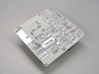
Other new developments, TDA1541A DAC module prototype was tested today. ..........
.......It has passive I/V conversion, using a Darlington stage that eliminates TDA1541A output compliance by creating a new (external) reference. The 500R wirewound mobius honeycomb passive I/V resistors provide 2Vpp without any active amplification,............
I really admire your work done so far... excellent job (the world need more engineers/ Inventor like you to progress better).
Does your developments so far allows interfacing with other TDA1541A design? Like those already in the vintage CD player? If so, how about parrallel TDA1541A with NOS or OS?
I will be particularly interested in the crystal and I/V conversion.
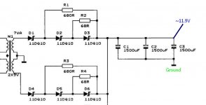
As for your 3-stage stepped rectifier, I just want to confirm with you that you are using it to replace a regular rectifier. A shortform of it will be as the attached?
I assume It can be used for almost any other circuits(amps, pre, CDP, etc) as long as the rectifier meets the demand of the circuit, right?
Just curious, Your crystal module integrated with the PCB capacitor you fabricated earlier?
Attachments
Hi fff0,
Parallel DACs do sound "impressive" but usually not transparent and clean.
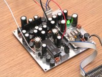
Well, why not have a look at the new TDA1541A DAC module that has just been completed. On-board voltage regulators and filters, can be connected to 3 x 12V batteries without any further power supply circuits. Module requires +10 ... 12V, -10 ... -12V and -20 ... -24V.
Extensive on-board power supply filtering ensures low noise levels.
DEM capacitors (currently using 1206 NPO SMD) are mounted underneath the TDA1541A and decoupling caps of each channel have dedicated GND plane that connects to pin 5 (AGND). DEM clock uses R-D injector at 1.4112 MHz (= bit clock).
Output circuit uses Darlington stage to create external reference that allows pure passive I/V conversion (2Vpp across 500R) without the limitations of TDA1541A output compliance.
It has I2S attenuators and Dynamic Jitter attenuators installed.
4-crystal superclock / synchronous reclocker is located close to the DAC chip where it belongs. Clock output (11.2896 MHz) can be used to slave the source.
The compact module measures only 10 x 10cm.
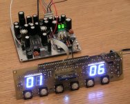
Second picture shows the TDA1541A module being driven by the SD-transport.
Does your developments so far allows interfacing with other TDA1541A design? Like those already in the vintage CD player? If so, how about parrallel TDA1541A with NOS or OS?
Parallel DACs do sound "impressive" but usually not transparent and clean.
Well, why not have a look at the new TDA1541A DAC module that has just been completed. On-board voltage regulators and filters, can be connected to 3 x 12V batteries without any further power supply circuits. Module requires +10 ... 12V, -10 ... -12V and -20 ... -24V.
Extensive on-board power supply filtering ensures low noise levels.
DEM capacitors (currently using 1206 NPO SMD) are mounted underneath the TDA1541A and decoupling caps of each channel have dedicated GND plane that connects to pin 5 (AGND). DEM clock uses R-D injector at 1.4112 MHz (= bit clock).
Output circuit uses Darlington stage to create external reference that allows pure passive I/V conversion (2Vpp across 500R) without the limitations of TDA1541A output compliance.
It has I2S attenuators and Dynamic Jitter attenuators installed.
4-crystal superclock / synchronous reclocker is located close to the DAC chip where it belongs. Clock output (11.2896 MHz) can be used to slave the source.
The compact module measures only 10 x 10cm.
Second picture shows the TDA1541A module being driven by the SD-transport.
Attachments
John, in the above photo are you using LVDS or other type of transmission between boards? If not using drivers, what is the max length cm that you suggest for DIYr who use dac board with the master clock slaved to transport board before SQ degrades? What kind of connectors are you using and why not twisted pair instead of flat ribbon?
Regarding the TDA1541a board what is the output impedance at 2Vout? What is DC offset on the output?
Great to see your offerings up on the website. Congratulations!
Regarding the TDA1541a board what is the output impedance at 2Vout? What is DC offset on the output?
Great to see your offerings up on the website. Congratulations!
Folks.
Just got back from Johns place. (to pick up some little toys )
Had a chance to listen to a complete player with with 1543 and his new 1541
board.
Conclusion of the day:
The 1543 sounded 100% identical (I couldn't hear a difference) if run off batteries (12V SLA) compared to the 1541 running off "mains".
(A/B testing could be done very well by switching inputs on Johns player from a remote control and running the same material in sync)
I've been really surprised about the result. I didn't expect the 1543 en par with the 1541.
In the past the battery supply has always been better. (Which is still the case if you look at the 1543 only)
The 1541 was not 100% finished though (free air cabling and not the final PS hooked up)
Open question: How would a 1541 sound, fed by batteries? There might be a slight chance that the 1541 beats the 1543 However a battery supply for a 1541 ( 3*12V) will be much more complicated to handle.
Above finding makes sense according to John, since the 1543 is more sensitive to the quality of power.
I think John has done a great Job.
Latest Thursday I can report how it sounds on my system.
Just got back from Johns place. (to pick up some little toys
) Had a chance to listen to a complete player with with 1543 and his new 1541
board.
Conclusion of the day:
The 1543 sounded 100% identical (I couldn't hear a difference) if run off batteries (12V SLA) compared to the 1541 running off "mains".
(A/B testing could be done very well by switching inputs on Johns player from a remote control and running the same material in sync)
I've been really surprised about the result. I didn't expect the 1543 en par with the 1541.
In the past the battery supply has always been better. (Which is still the case if you look at the 1543 only)
The 1541 was not 100% finished though (free air cabling and not the final PS hooked up)
Open question: How would a 1541 sound, fed by batteries? There might be a slight chance that the 1541 beats the 1543
However a battery supply for a 1541 ( 3*12V) will be much more complicated to handle.Above finding makes sense according to John, since the 1543 is more sensitive to the quality of power.
I think John has done a great Job.
Latest Thursday I can report how it sounds on my system.
I think John has done a great Job.
Latest Thursday I can report how it sounds on my system.
He sure did and i hope you will enjoy it as much as i do. Since 3 weeks now i listen to the 1543 DAC and never had a boring moment. It's the first DAC that keeps me listening without hesitating. The level of details is outstanding. The environment in the soundstage is like a real experience.
Next week i hope to get the 1541 version to compare it with the 1543 at my home. Both feeded by a squeezebox and on batteries. I will report here.
Last edited:
Hi riotubes,
No I use plain 3.3V signals, I try to keep all (digital and analogue) signal paths as simple as possible. Drivers would add jitter and cause extra power supply pollution (switching currents).
It's always best to keep I2S interlinks as short as possible. I tested 1 meter ribbon cable I2S interlink and it works fine, though not advisable, but it shows the interlink isn't very critical due to 1.4112 MHz being the highest clock frequency used.
Biggest problem would be master clock (11.2896 MHz) that is required to slave the source. Jitter levels will increase with interlink length due to various reasons like increased (capacitive) clock load, and interference picked-up by interlink.
Practical interlink length should be kept between 5 and 20 cm.
I use sockets that match the 2.45mm pitch headers. Wires are soldered directly to the pins.
I tested twisted pair, ribbon cable and coax. I couldn't hear any difference in sound quality. I settled for ribbon cable connected as follows:
GND, DATA, GND, WS, GND, BCK, GND.
DATA is kept as far away from the BCK signal (sample timing) as possible.
Output impedance (2Vpp output) equals approx. 500 Ohms. DC offset equals Vsupply - (ibias * Riv), 5-(0.002 * 500) = 4V. With 700R I/V resistor (2.8Vpp), DC offset equals 5-(0.002 * 700) = 3.6V. So output coupling cap is required.
Output amplitude can be further increased using a clean external DC voltage. 10 K Ohm I/V resistor for example would generate 40Vpp and would require approx. 45V DC power supply for passive I/V resistor only. These higher output amplitudes could be used to directly drive a (FET) unity gain power buffer that in turn drives a speakers or headphones. The advantage is that no active amplification would be required at all.
This can be done with the existing TDA1541A module by connecting the passive I/V resistors externally. Maximum external I/V resistor power supply voltage would be approx. 100 volts DC (90Vpp output amplitude with 22K5 passive I/V resistor).
John, in the above photo are you using LVDS or other type of transmission between boards? If not using drivers, what is the max length cm that you suggest for DIYr who use dac board with the master clock slaved to transport board before SQ degrades? What kind of connectors are you using and why not twisted pair instead of flat ribbon?
No I use plain 3.3V signals, I try to keep all (digital and analogue) signal paths as simple as possible. Drivers would add jitter and cause extra power supply pollution (switching currents).
It's always best to keep I2S interlinks as short as possible. I tested 1 meter ribbon cable I2S interlink and it works fine, though not advisable, but it shows the interlink isn't very critical due to 1.4112 MHz being the highest clock frequency used.
Biggest problem would be master clock (11.2896 MHz) that is required to slave the source. Jitter levels will increase with interlink length due to various reasons like increased (capacitive) clock load, and interference picked-up by interlink.
Practical interlink length should be kept between 5 and 20 cm.
I use sockets that match the 2.45mm pitch headers. Wires are soldered directly to the pins.
I tested twisted pair, ribbon cable and coax. I couldn't hear any difference in sound quality. I settled for ribbon cable connected as follows:
GND, DATA, GND, WS, GND, BCK, GND.
DATA is kept as far away from the BCK signal (sample timing) as possible.
Regarding the TDA1541a board what is the output impedance at 2Vout? What is DC offset on the output?
Output impedance (2Vpp output) equals approx. 500 Ohms. DC offset equals Vsupply - (ibias * Riv), 5-(0.002 * 500) = 4V. With 700R I/V resistor (2.8Vpp), DC offset equals 5-(0.002 * 700) = 3.6V. So output coupling cap is required.
Output amplitude can be further increased using a clean external DC voltage. 10 K Ohm I/V resistor for example would generate 40Vpp and would require approx. 45V DC power supply for passive I/V resistor only. These higher output amplitudes could be used to directly drive a (FET) unity gain power buffer that in turn drives a speakers or headphones. The advantage is that no active amplification would be required at all.
This can be done with the existing TDA1541A module by connecting the passive I/V resistors externally. Maximum external I/V resistor power supply voltage would be approx. 100 volts DC (90Vpp output amplitude with 22K5 passive I/V resistor).
Hi soundcheck,
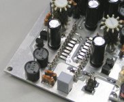
The prototype TDA1541A DAC module PCB was just completed so I had little time to tune it. I didn't receive the required 33nF SMD 1206 PPS decoupling caps in time so I had to use 4.7nF NPO for testing instead. Power supply was a quick and dirty plain mains power supply that produced plenty of ripple voltage. Audio interlinks were over 50cm long and picked up interference. I also created a ground loop by connecting an external mains-powered device to the ISD player (I used auxiliary analogue input on the ISD player to connect TDA1541A DAC module). So it's obvious that the module wasn't performing optimally.
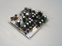
After installing the 14 x 33nF decoupling caps (picture), the TDA1541A module already performed better compared to the TDA1543 DAC module. There was better bass and more detail (refinement) similar to the breadboard prototype setup that already had 33nF film decoupling caps (leaded) installed. I also attached some other views of the new TDA1541A DAC module.
TDA1541A has different ripple rejection on each of the 3 power supplies (Philips datasheet page 7)
+5V, -76dB
-5V, -84dB
-15V, -58dB
-15V is most sensitive to power supply pollution, since I connect I/V resistors to +5V, this voltage needs to be clean too. The -5V (digital) power supply of the TDA1541A is not that critical.
I know that a battery power supply eliminates ground loops and provides a ripple-free DC supply. I had some 12V 2Ah and 18Ah lead-acid batteries laying around so I connected these to the TDA1541A DAC module:
12V / 18Ah battery for 5V supply (DAC and SD-transport).
12V / 2Ah battery for -5V supply (DAC).
12V / 2Ah battery (in series with the one for -5V) for -15V supply (DAC).
I used a 5V regulator to power the SD-transport since it has no on-board 5V regulator.
I now had both, SD-transport and TDA1541A DAC running on battery power supply, completely isolated from the mains.
It sounds extremely clean, in fact I never heard a TDA1541A perform like this before!
Module average power consumption:
SD-transport module:
Logic section, 5V / 100mA (0.5W)
Display, 5V / 45mA (0.225mW)
TDA1541A DAC module:
+5V / 60mA (0.3W)
-5V / 45mA (0.225W)
-15V / 30mA (0.45W)
+5V supply current (total) 205mA
-5V supply current (also supplies -15V) 75mA
-15V supply current 30mA
for maximum efficiency (smallest size, longest battery life) battery capacity (5V : -5V : -15V) would be 6.83 : 2.5 : 1
So if we choose 12V 2Ah battery for -15V, it will provide approx. 67 hours of battery life.
Battery for -5V would need to have at least 2 * 2.5 = 5Ah, 12V / 7.2Ah comes closest.
Battery for +5V would need to have at least 2 * 6.83 = 13.66Ah, 12V / 18Ah comes closest.
So with 3 different 12V batteries, 2Ah, 7.2Ah and 18Ah can power both TDA1541A DAC module and SD-transport for approx. 67 hours. When listening average of 5 hours every day, the battery pack will last for almost 2 weeks!
The 1541 was not 100% finished though (free air cabling and not the final PS hooked up)
Open question: How would a 1541 sound, fed by batteries? There might be a slight chance that the 1541 beats the 1543 However a battery supply for a 1541 ( 3*12V) will be much more complicated to handle.
The prototype TDA1541A DAC module PCB was just completed so I had little time to tune it. I didn't receive the required 33nF SMD 1206 PPS decoupling caps in time so I had to use 4.7nF NPO for testing instead. Power supply was a quick and dirty plain mains power supply that produced plenty of ripple voltage. Audio interlinks were over 50cm long and picked up interference. I also created a ground loop by connecting an external mains-powered device to the ISD player (I used auxiliary analogue input on the ISD player to connect TDA1541A DAC module). So it's obvious that the module wasn't performing optimally.
After installing the 14 x 33nF decoupling caps (picture), the TDA1541A module already performed better compared to the TDA1543 DAC module. There was better bass and more detail (refinement) similar to the breadboard prototype setup that already had 33nF film decoupling caps (leaded) installed. I also attached some other views of the new TDA1541A DAC module.
TDA1541A has different ripple rejection on each of the 3 power supplies (Philips datasheet page 7)
+5V, -76dB
-5V, -84dB
-15V, -58dB
-15V is most sensitive to power supply pollution, since I connect I/V resistors to +5V, this voltage needs to be clean too. The -5V (digital) power supply of the TDA1541A is not that critical.
I know that a battery power supply eliminates ground loops and provides a ripple-free DC supply. I had some 12V 2Ah and 18Ah lead-acid batteries laying around so I connected these to the TDA1541A DAC module:
12V / 18Ah battery for 5V supply (DAC and SD-transport).
12V / 2Ah battery for -5V supply (DAC).
12V / 2Ah battery (in series with the one for -5V) for -15V supply (DAC).
I used a 5V regulator to power the SD-transport since it has no on-board 5V regulator.
I now had both, SD-transport and TDA1541A DAC running on battery power supply, completely isolated from the mains.
How would a 1541 sound, fed by batteries? There might be a slight chance that the 1541 beats the 1543 However a battery supply for a 1541 ( 3*12V) will be much more complicated to handle.
It sounds extremely clean, in fact I never heard a TDA1541A perform like this before!
Module average power consumption:
SD-transport module:
Logic section, 5V / 100mA (0.5W)
Display, 5V / 45mA (0.225mW)
TDA1541A DAC module:
+5V / 60mA (0.3W)
-5V / 45mA (0.225W)
-15V / 30mA (0.45W)
+5V supply current (total) 205mA
-5V supply current (also supplies -15V) 75mA
-15V supply current 30mA
for maximum efficiency (smallest size, longest battery life) battery capacity (5V : -5V : -15V) would be 6.83 : 2.5 : 1
So if we choose 12V 2Ah battery for -15V, it will provide approx. 67 hours of battery life.
Battery for -5V would need to have at least 2 * 2.5 = 5Ah, 12V / 7.2Ah comes closest.
Battery for +5V would need to have at least 2 * 6.83 = 13.66Ah, 12V / 18Ah comes closest.
So with 3 different 12V batteries, 2Ah, 7.2Ah and 18Ah can power both TDA1541A DAC module and SD-transport for approx. 67 hours. When listening average of 5 hours every day, the battery pack will last for almost 2 weeks!
Attachments
John,
I'm interested in your use of batteries as I favour Lithium Nano phosphate types for my low voltage & digital supplies but I haven't really seen too much credible research on battery noise. Have you conducted noise measurements?
I know there is a link on TNT that everybody cites when claiming that SLA batteries are not low noise when current is being drawn from them but I'm not convinced of the rigour of the that conclusion & there are some other papers that contradict this conclusion, for some battery types anyway. Cookies Required
An interesting short discussion about SLA battery noise: Lead Acid Battery Noise
Last edited:
Hi jkeny,
Main advantages of battery power supply over mains power supplies are elimination of ground loops (isolated power source), and no ripple (50 ... 120Hz) voltage. When connecting two mains-powered devices, LF ... HF interference will start to flow between both units. This interference is super-imposed on whatever signals are carried from one device to the other. That's why in my humble opinion, ultimate performance is very difficult to achieve when using separate mains powered "boxes" connected through interlinks.
If you use a battery power supply and connect GND of a mains power supply to the (minus) of the battery, creating a ground loop, battery performance will drop considerably.
The TNT SLA noise measurements may not be representative for all SLA batteries, and actual noise under load can be a lot lower.
This noise also can be filtered to some extent, but the advantages mentioned above, usually result in improved performance over mains power supplies, regardless of typical battery noise.
I use SLA batteries because they are reliable and cheap. Charging isn't very critical either.
I'm interested in your use of batteries as I favour Lithium Nano phosphate types for my low voltage & digital supplies but I haven't really seen too much credible research on battery noise. Have you conducted noise measurements?
I know there is a link on TNT that everybody cites when claiming that SLA batteries are not low noise when current is being drawn from them but I'm not convinced of the rigour of the that conclusion & there are some other papers that contradict this conclusion, for some battery types anyway.
Main advantages of battery power supply over mains power supplies are elimination of ground loops (isolated power source), and no ripple (50 ... 120Hz) voltage. When connecting two mains-powered devices, LF ... HF interference will start to flow between both units. This interference is super-imposed on whatever signals are carried from one device to the other. That's why in my humble opinion, ultimate performance is very difficult to achieve when using separate mains powered "boxes" connected through interlinks.
If you use a battery power supply and connect GND of a mains power supply to the (minus) of the battery, creating a ground loop, battery performance will drop considerably.
The TNT SLA noise measurements may not be representative for all SLA batteries, and actual noise under load can be a lot lower.
This noise also can be filtered to some extent, but the advantages mentioned above, usually result in improved performance over mains power supplies, regardless of typical battery noise.
I use SLA batteries because they are reliable and cheap. Charging isn't very critical either.
John I think there is much more to it.
The mains supply is dirty like hell. The sine wave is not a sinewave. 50/60Hz is not 50/60Hz. Tons of reactive forces, DC, materials, connectors and other flaws causing
stress to that source. All this is slowing down and degrading the supply.
All this is gone by introducing a battery. By adding a fast cap-buffer to the battery it'll be hard to beat.
We should think about what e.g. a simple high quality mains cable (xxx$) will do the sound. And not just on "el cheapo" equipment.
We can continue with all kind of other nonsense you can put in your mains setting at home. ( Been there done that - straight silver cable to the mains distribution as one of the weired things I've done in earlier days. )
IMO it can't go better and cheaper with a well done battery supply. All my little 10W amps
are also fed by batteries.
The mains supply is dirty like hell. The sine wave is not a sinewave. 50/60Hz is not 50/60Hz. Tons of reactive forces, DC, materials, connectors and other flaws causing
stress to that source. All this is slowing down and degrading the supply.
All this is gone by introducing a battery. By adding a fast cap-buffer to the battery it'll be hard to beat.
We should think about what e.g. a simple high quality mains cable (xxx$) will do the sound. And not just on "el cheapo" equipment.
We can continue with all kind of other nonsense you can put in your mains setting at home. ( Been there done that - straight silver cable to the mains distribution as one of the weired things I've done in earlier days.
)IMO it can't go better and cheaper with a well done battery supply. All my little 10W amps
are also fed by batteries.
- Status
- This old topic is closed. If you want to reopen this topic, contact a moderator using the "Report Post" button.
- Home
- Source & Line
- Digital Source
- Lossless SD-card player