Hey Wynand, yuo may find the RS site a handy tool for stuff like that.. not saying you should buy from them, but they do have quite complete information on their products, have a look at a few pots on there to get a general idea... also you do get quite small pots.. I accidentaly ordered the wrong one once, and got a dual pot of which the 6 pins fill 2 x 3 matrix on veroboard 
Try to get the datasheet for the pot. Probably you have a 0.1" grid.Wynand said:Does the PCB look OK?
Does anyone know what the standard pin spacing is between the three pins of each pot on a dual gang pot?
The layout looks pretty good but I'm not sure it's wise to have the starground as you have done. I would try to have left and wright channel more compact and shorter ground paths. I would also insert 100-220 ohms in series with the opamp output as a safety precaution.
If you do this pcb by yourself, why don't you do it with groundplane? Just put tape on the component side. You can use any platic tape, transperant office tape or better brown parcel tape. Check how I have done.
http://home5.swipnet.se/~w-50674/hifi_pics/hifi_100pr/qrv01_old.jpg
If you do this pcb by yourself, why don't you do it with groundplane? Just put tape on the component side. You can use any platic tape, transperant office tape or better brown parcel tape. Check how I have done.
http://home5.swipnet.se/~w-50674/hifi_pics/hifi_100pr/qrv01_old.jpg
Star ground is good for "DC"(=not HF) but I have serious doubts over 1 MHz where the decoupling is active. Groundplane has much lower impedance than normal traces.
1 nH per cm what does this result if the trace is 5-10 cm? ( 2*pi*f*L). The importat rule is not to draw high currents across sensitive areas, but otherwise keep things compact.
At 1 MHz you'll have 26 uOhms/square in a groundplane
A wire has 31 milliohms at 5 cm trace.
1 nH per cm what does this result if the trace is 5-10 cm? ( 2*pi*f*L). The importat rule is not to draw high currents across sensitive areas, but otherwise keep things compact.
At 1 MHz you'll have 26 uOhms/square in a groundplane
A wire has 31 milliohms at 5 cm trace.
Revision Time
I've actually managed to get to an internet cafe!!!
I did this rev quickly.
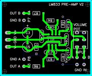
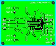
There's a resistor on the output and theres a ground plane on the bottom. Putting the plane on top is a matter of seconds but I thought that not everybody has two layer boards (Thats if anybody would use this.).
Anyway, if its better on top( ) please tell me.
The input traces are way shorter now. In fact, they're all pretty short.
Please rip it apart and tell me whats wrong/right on the layout.
Peace to all.
Tomorrow!!!
p.S. the first pic is without the ground plane to make it easier to see the component numbers.
I've actually managed to get to an internet cafe!!!
I did this rev quickly.
There's a resistor on the output and theres a ground plane on the bottom. Putting the plane on top is a matter of seconds but I thought that not everybody has two layer boards (Thats if anybody would use this.).
Anyway, if its better on top(
) please tell me.The input traces are way shorter now. In fact, they're all pretty short.
Please rip it apart and tell me whats wrong/right on the layout.
Peace to all.
Tomorrow!!!
p.S. the first pic is without the ground plane to make it easier to see the component numbers.
Attachments
And an unfiltered input may ruin every effort to get a RF-aware layout. Also, the potentiometer will go noisy relatively quickly if the bias currents of the op-amp inputs are left flowing through the wipers (electrolysis), so wiper coupling capacitors are recommended (or maybe an op-amp with JFET inputs...)
One condition for a good groundplane is that it really is a plane, a whole plane. Now you have cut it in small pieces. If you have the opportunity, make a double sided board with the "tape method". Have you checked out how I did? See the picture above.
As Eva says, HF filter ot at least room for it, at the input is a good idea.
About the pot, it's also true and even more true when the input bias currents are rather high like in your case but not to worry because you have this current isolated by the cap.
As Eva says, HF filter ot at least room for it, at the input is a good idea.
About the pot, it's also true and even more true when the input bias currents are rather high like in your case but not to worry because you have this current isolated by the cap.
Carlos, don't forget where Wynand is. Your pcb will work pretty good for opamps with slew rates up to 20-50 V/us which is quite sufficient for now. Start with this and see how it goes. If you listen to my advice to put tape on the componentside you'll get a very good groundplane and this will unsure a good voltage supply.
I have made homebrewed pcb's with groundplanes as the picture and I have never had any problems related to bad decoupling.
The ground resistor isn't very important because you don't have any real power ground due to small currents.
I have made homebrewed pcb's with groundplanes as the picture and I have never had any problems related to bad decoupling.
The ground resistor isn't very important because you don't have any real power ground due to small currents.
- Status
- This old topic is closed. If you want to reopen this topic, contact a moderator using the "Report Post" button.
- Home
- Amplifiers
- Chip Amps
- LM833 any good?