Re: Lets get 2 the schematic
If you want to minimize the offset from the LM833 both inputs should "see" the same resistance and this means that you should have 47 k between the inverting input and the output but since 47 k is pretty much I'll suggest that you decouple it with 100 nF for starters. The is to cancel out the input bias currents which you have.
If you want to minimize the offset from the LM833 both inputs should "see" the same resistance and this means that you should have 47 k between the inverting input and the output but since 47 k is pretty much I'll suggest that you decouple it with 100 nF for starters. The is to cancel out the input bias currents which you have.
peranders said:So if the thread starter is after something alright I'll guess a LM833 will do but hardly if he is after "spitzenklasse".
Is that something you load into a bazooka?

Some german words sounds really nice in my ears.
http://www.websters-online-dictionary.org/translation/spitzenklasse
http://www.websters-online-dictionary.org/translation/spitzenklasse
Carlosfm, It’s not exactly a matter of will, its just that it was consumer-produced and sold and I have some reservations because of that :-(
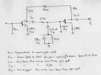
But there is no need for my exact choices, and it’s easy to experiment with this concept and get good results; Look at the attached file to have an idea. I have also written there how caps in the passive riaa affect the frequency range – it is in this stage that we have the best tone controls if needed btw) Build it on a breadboard and experiment (listening, off course, don't let a Spice model decide for you. Some care should be taken in the first to second gain ratio, some care should be taken in pcb work and grounding, good work in the psu, g o o d grounding topology and implementation, but I presume you are an expert in these matters, then the usual stuff, some wima caps for instance etc. ;-)
It’s a ‘zen’ kind of phono circuit which if implemented with care can give pleasure
But there is no need for my exact choices, and it’s easy to experiment with this concept and get good results; Look at the attached file to have an idea. I have also written there how caps in the passive riaa affect the frequency range – it is in this stage that we have the best tone controls if needed btw
) Build it on a breadboard and experiment (listening, off course, don't let a Spice model decide for you. Some care should be taken in the first to second gain ratio, some care should be taken in pcb work and grounding, good work in the psu, g o o d grounding topology and implementation, but I presume you are an expert in these matters, then the usual stuff, some wima caps for instance etc. ;-)It’s a ‘zen’ kind of phono circuit which if implemented with care can give pleasure
Attachments
When reasonably fast op-amps are used in complex filters including a lot of components and long tracks, or in circuits that include potentiometers, it's always a good idea to put a small capacitor (47pf or so) between OUT and IN- to force unity gain at high frequencies and to improve rejection of the RF picked by the own circuit. Otherwise there would be a potential risk of parasitistic oscillation. Of course, this approach is only valid for unity-gain stable op-amps. Note that the capacitor should be sized to have little or no impact at audio frequencies.
 )
)Wynand said:While I'm implementing a HP Filter would it be ok to put a LP filter straight afterwards.
If so what frequency or values is good?
If you are lazy and don't want to do so much math, just put in this network into LTSpice, freeware from Linear Tech.
http://www.linear.com/company/software.jsp
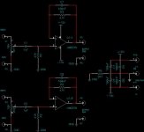
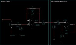
Wynand said:And this is the schematic so far
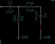
'100nF' parallel with 47.000 Ohm ?
In my calculations it should be 22/33pF ( possibly max 47pF )
33pF // 47k = 102600 Hz
Application Note 346 High-Performance Audio Applications of The LM833
Yes 100 nF for creating low impedance (and noise) in the audio band or as low as possible.
47 k or something is for creating as low offset as posssible without any trimming.
I'll guess you have missed the purpose of the 22 pF or whatevercap, and this is for compensation of the input capacitance. High value of the feedback resistor => easier to get instability. The cap is for reducíng this.
If you want to explore this, take an ideal opamp and insert a cap between the input and put all this into LTSpice.
peranders said:Yes 100 nF for creating low impedance (and noise) in the audio band or as low as possible.
If you say so.
But I would use 22pF in parallel with 47kOhm.
Nobody could even force me, with violence, into use 100nF
peranders said:Yes 100 nF for creating low impedance (and noise) in the audio band or as low as possible.
If you want to explore this, take an ideal opamp and insert a cap between the input and put all this into LTSpice.
Run it in your own LTSpice.
(
I do not have it. I do not use it. I do not need it. )100nF / 47 KOhm
and
take a compare to my
22pF / 47 KOhm
... and then you tell me what is worse with my choice.
To make a real evaluation
Put your LTSpice 'ideal op-amp' LM833 into a PCB and use it.
And tell me what your ears find is so bad with 22pF.
- Status
- This old topic is closed. If you want to reopen this topic, contact a moderator using the "Report Post" button.
- Home
- Amplifiers
- Chip Amps
- LM833 any good?