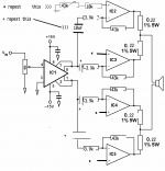
Finally,I understand the mistakes of my schematic,and I`ve given up using this schematic and am planing to build the amp using your schematic,but I have some question about it.Is U1 DRV134?
Do I need to put a buffer before the DRV134?Where do I put the decoupling cap(I am not sure if it is called decoupling cap,I mean the cap to block the DC )?before or after the DRV134?
Thank you very much!
Do I need to put a buffer before the DRV134?Where do I put the decoupling cap(I am not sure if it is called decoupling cap,I mean the cap to block the DC )?before or after the DRV134?
Thank you very much!
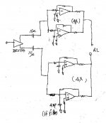
I have been doing similar concept but it is based on non inverting amp. Here is the schematic that I am using. It is Brians GT amp. I am connecting two of this boards LM4780 paralleled per one side of the bridge. I am not using DRV 134 because I am supplying balanced signal.
My question for jaudio is: on this schematic, where I could put trimpot for DC offset adjustment. Would that be R4 - 22.1 K? I am having hard time putting these boards together paralleled. Any time I try to parallel two boards that have on them 0.1 ohm on each side of the LM4780 chip - they oscillate. Than I started adding extra resistors between boards, and I ended up with 0.5 ohm between. I do not understand why is this happening. Each board because of some reason produces about 150mV DC, but in bridged configuration that gets canceled.
I posted this question in this link, but I never got full understanding of the problem.http://www.diyaudio.com/forums/showthread.php?s=&threadid=54575&perpage=10&highlight=&pagenumber=1
post #7
Attachments
In inverted mode the input resistor sets impedance. In non-inverted mod impedance is set in the chip, normally it is very high.
Put a trimpot on the (-) signal input and you will get noise.
Here is something Thomasfw posted that might help
I didnt try it,so I dont know if it will work.
Put a trimpot on the (-) signal input and you will get noise.
Here is something Thomasfw posted that might help
I didnt try it,so I dont know if it will work.
Attachments

Nice catch. It's no wonder that the amp is oscillating. Do people even bother to read datasheets anymore?The lm3886 needs a gain of aleast 10.
Upupa Epops said:Don't make it with DRV 134 - it's not quite good sounding circuit.
Pavel-
So what do you suggest as a replacement?
mateo88 said:
i.e., can you just take two of image 5.2.1 in the AN-1192 datasheet and parallel them?
Two bridged amp in parallel would still require output resistors. Image 7.2.4 would be better.
- Status
- This old topic is closed. If you want to reopen this topic, contact a moderator using the "Report Post" button.
- Home
- Amplifiers
- Chip Amps
- Lm3886 Bpa