Yes that's right. Source output impedance should be around 50ohmsmateo88 said:Ok, that makes sense. So if I was using a source that could easily handle the 500 ohm impedance, I really wouldn't need u1 at all, correct?")
mateo88 said:
Sorry for the dumb questions, but thanks for answering them for me!
Questions are only dumb,If you have them and dont ask.
Your Welcome
AR2 said:. I have PS board for each LM board, and each one is snubberized (all together 4 PS boards per channel) I bypassed all caps with .1uF and I have 6300uF per rail per board.
Try using one PS per channel.
The lm3886 needs a gain of aleast 10. If you want to use a gain of four use the OPA chips (549 or 541). The OPA chips cost 3 times as much as lm3886. You can leave out the input caps,but you might have a problem with dc offset.
Hi Jaudio, Macboy and all,
Long time no see and how are you ?
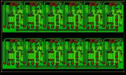
I just received the DRV134 from US, I just finished the PCB layout during the Summer Holiday !
I think you miss understand my draft. The "4X" means use 4 pcs
of LM3886.
Thank You all your valuable advices in this project !!
How about the low voltage 6229, what is the questions ?
Thomas
Dear Jaudio,
Attached the PCB Layout, but I have not checked
I will try my best to answer your tube project.
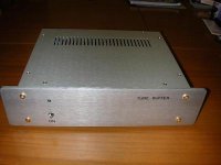
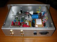
By the way, I have just made a tube buffer for my friend.
It connect in between DVD player (Made in China, HKD499) and
a AV amp.
You can't belive how great it is !!!!!!
I plan to do this
Pass Lab Pre-Amp + Tube Buffer+ BPA 200 or
CD player + Tube Buffer + Pass Lab Pre Amp +BPA 200
Thomas
Attached the PCB Layout, but I have not checked
I will try my best to answer your tube project.
By the way, I have just made a tube buffer for my friend.
It connect in between DVD player (Made in China, HKD499) and
a AV amp.
You can't belive how great it is !!!!!!
I plan to do this
Pass Lab Pre-Amp + Tube Buffer+ BPA 200 or
CD player + Tube Buffer + Pass Lab Pre Amp +BPA 200
Thomas
Dear Jaudio,
Attached the PCB Layout, but I have not checked
I will try my best to answer your tube project.
By the way, I have just made a tube buffer for my friend.
It connect in between DVD player (Made in China, HKD499) and
a AV amp.
You can't belive how great it is !!!!!!
I plan to do this
Pass Lab Pre-Amp + Tube Buffer+ BPA 200 or
CD player + Tube Buffer + Pass Lab Pre Amp +BPA 200
Thomas
Attachments
thomasfw said:Dear Jaudio,
By the way, I have just made a tube buffer for my friend.
It connect in between DVD player (Made in China, HKD499) and
a AV amp.
You can't belive how great it is !!!!!!
Thomas
Ok I cant resist. Can you Email the schematics to me?
Thanks
please help me. I desperately need a schematic of JR model 12-concentra.
pls.mail me at jkraxi@yahoo.com
thx, JAY
pls.mail me at jkraxi@yahoo.com
thx, JAY
jaudio said:No buffer needed.
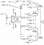
The caps go bewteen drv134 output and input resistor of each lm3886. Be sure to match all resistor as close as possible
Hi JAUDIO,
For the circuit you shown in #62, can I replace the 10uf cap with 1uf? I think the purpose of 10uf is to block DC. Correct?
jaudio said:HI
That cap also act as part of a high pass filter. If you use a 1uf cap with the same resistor value then the cutoff frequency will be
159155/(R*frequency)=C(Capacitor value)
for a 20hz cutoff frequency,you should divend by 4.
5Hz would be your target
Thank a lot JAUDIO, I think I may misunderstand something
With R=3900, C=1uF, this equation would give
the cutoff freq = 159155/(3900x0.000001) Hz????????
Attachments
Hello
For a 1uf cap and a resistor value of 3.9k, the cutoff frequency is 40Hz, which is much too high.
Let say you want a cutoff frequency of 15hz
1. 15Hz/4=3.75Hz
2. 159155/(3900*3.75)=11.3uf
R is the resistor on the inverted input
Remember,I used 3.9k on the schematic
for an example,your value may be different.
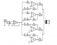
Mrpong said:According to this original BPA200 schematic, I think we can use trimpots at the + input PINs of U3 and U4. However how can we use trimpot at U1 and U2?
Add trimpots the U1 and U2 wont work, the impedance in the chip is too high.
In the schematic, I posted all the chips are in the inverted mode.
If you use the original BPA200 schematic, you won’t be able to adjust the dc offset. There are a few things you can do to minimize the offset
Increase the output resistor value to .3 to.5 ohms
Use chips with similar dc offset (You will have to buy more chips to match them)
servo s
You should use the original Bpa200 schematic or the schematic I posted. I don’t think the schematics can be mixed together
- Status
- This old topic is closed. If you want to reopen this topic, contact a moderator using the "Report Post" button.
- Home
- Amplifiers
- Chip Amps
- Lm3886 Bpa