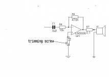
It go bewteen the + signal input and ground. I connect two of the pin of the trimpot together,that is connect to + signal input and the remaining pin is connected to ground. This is for inverted mode amp.
Would You please post the schematic !
Many thanks !
Thomas
I do know that the concentra is inverted and uses the drv134.
Do you know they add "Buffer OP" in front of "DRV134" or after it ?
How do you calculate the feedback R (470k/16k) in your ver. ?
As shown in BPA 200 document, thet are (21.5K/1K).
Thanks !
Thomas
Your welcome
I dont know if concentra uses buffer in front of drv134.
I have the gain 13 on the (+) side and 13 on the (-) that adds up the 26.
The example I post was just an example.
If you use bridged parallel, you must use a lower gain than normal because both side adds up.
I dont know if concentra uses buffer in front of drv134.
I have the gain 13 on the (+) side and 13 on the (-) that adds up the 26.
The example I post was just an example.
If you use bridged parallel, you must use a lower gain than normal because both side adds up.
I can answer that.thomasfw said:Dear jaudio,
I don't understand why the "trim pot"(R3) value is equal to "Feedback"(RF) ?
because :
R3 should equal to :
R3 = (Rin * RF)/ (Rin + RF)
Best Regards !
Thomas
Your equation is correct. To minimize the DC offset, you should try to make the resistance to each input pin the same (since the bias currents at each pin are in theory, the same), so:
R3 = (Rin * RF)/ (Rin + RF)
However, note that we are talking about DC offset, and therefore, we must use DC impedances for Rin and Rf, not necessarilly just the resistor values. Note that Rin has a capacitor in series with it, and that changes things. That means that at DC, the impedance (of this R-C network) is infinite (or nearly infinite). Then R3 = ( Rf in parallel with infinity ), which is R3 = Rf.
jaudio also recommends using a trimpot for R3. This is because the bias currents for each input pin are not exactly the same for any given chip. The trimpot lets you adjust the resistance to compensate for variations in bias currents for a particular chip.
It depends on the amount of gain,that you want. In inverted mode, an input resistor of 10k and a Rf resistor of 220k will give a gain of 22. So with 1volt in you get 22 out. In bridge mode your get(-22)+(+22)=44. With that amount of
gain get lots of noise. Lower gain would be better.
Just match dc offset with trimmer and match ballast resistors.
I hope this helps
gain get lots of noise. Lower gain would be better.
Just match dc offset with trimmer and match ballast resistors.
I hope this helps
Thank You For Your Fast Response !
Let me asked in detail :
Rf=200K, Rin=10K, Gain=20
Rf=20k, Rin=1K, Gain also=20
What is the different in between them ?
If I want the total Output=200W,8 ohm (after Paralell & Bridge)
and let the Vin= 1v.
What should I do with the Rf , Rin & Trim Pot ?
Many Thanks !
Thomas


")
Let me asked in detail :
Rf=200K, Rin=10K, Gain=20
Rf=20k, Rin=1K, Gain also=20
What is the different in between them ?
If I want the total Output=200W,8 ohm (after Paralell & Bridge)
and let the Vin= 1v.
What should I do with the Rf , Rin & Trim Pot ?
Many Thanks !
Thomas
In bridge mode your get(-22)+(+22)=44
Dear jaudio, macboy and all,
Please tell me what's wrong with my understanding
By theory, the Output of bridge amp= 4X of single amp
and what is the relationship in between what you said :
Let :total gain =40, Vin=1V, then Vout will be 40V and R=8ohm
Output W=(V*V)/R
= 40*40/8
=200W
Thomas
20k and 1k will have less noise.
You would need a gain of about 24(+24 + -24)
If you plan on making your own preamp,I would incease the preamp gain to 2v output and go with (+12 + -12)
I would go for 4K 48k and 50k trimmer.
If you plan on parallel six use a input resistor with more than 1k resistance.
You would need a gain of about 24(+24 + -24)
If you plan on making your own preamp,I would incease the preamp gain to 2v output and go with (+12 + -12)
I would go for 4K 48k and 50k trimmer.
If you plan on parallel six use a input resistor with more than 1k resistance.
Same gain, but different input impedance.Rf=200K, Rin=10K, Gain=20
Rf=20k, Rin=1K, Gain also=20
What is the different in between them ?
A 1K input impedance can place too much of a load on say, a CD player line-level output. But note that National's BPA amplifier design has buffered the input with an opamp, which has no difficulty driving a 1K input impedance (in fact, it drives four of them).
If you need a higher input impedance, then you will also need a higher feedback resistor to achieve the same gain . Note that higher resistances create more thermal noise (a.k.a. "resistor noise"). So if you increase it too much, then it will begin to add extra noise into the system, which you can hear as background hiss. (Another way to get high gain, without a high feedback resistance and the noise it makes, is to use a T-network feedback, but that's another thread in itself).
Correct, that a bridged amp will double the voltage at the speaker terminals, which, by P=V*V/R, gives 4 times the power (P). Note also that the current flowing through each of the amps is also doubled, which is in effect, the same as decreasing the load (speaker) impedance by half. An 8 ohm speaker connected to a bridged amp loads each 'side' of the bridged amp with a 4 ohm load. The National app note describes this and what you need to do about it when designing an amp.By theory, the Output of bridge amp= 4X of single amp
and what is the relationship in between what you said :
Let :total gain =40, Vin=1V, then Vout will be 40V and R=8ohm
Output W=(V*V)/R
= 40*40/8
=200W
However, your calculation of power above may be wrong. Make sure not to use the peak voltage in your calculations. To calculate RMS power, you must use the RMS voltage, which is (for a sinewave), the peak voltage divided by sqrt(2), or Vrms=Vpeak/1.4142
I'd suggest 3.9K and 47K, which are standard (E24) values.jaudio said:...
I would go for 4K 48k and 50k trimmer.
...
Also, it wouldn't hurt to use, say, a 43K resistor and a 10K trimmer in series. That would make adjustment a little easier by restricting the adjustment range to 43K - 53K.
I'd suggest 3.9K and 47K, which are standard (E24) values.
What is the (E24) ?
43K resistor and a 10K trimmer in series
I will take your advise !
National's BPA amplifier design has buffered the input with an opamp, which has no difficulty driving a 1K input impedance (in fact, it drives four of them).
I plan to use "DRV134" and all LM3886 use "Inverted", what will you think ?
My local time is 2:00 a.m., and I need to go to sleep !
Thomas


- Status
- This old topic is closed. If you want to reopen this topic, contact a moderator using the "Report Post" button.
- Home
- Amplifiers
- Chip Amps
- Lm3886 Bpa