")
I'm thinking I may just parallel on the output another one of the 470uF SEPC caps (10mOhm ESR) I have here.
My goal of modelling this circuit structure for higher current implementation seems to have hit a wall - I can't for the life of me find a Spice model for the LM138/LM338. Modelling the LT1084 should be possible.
My goal of modelling this circuit structure for higher current implementation seems to have hit a wall - I can't for the life of me find a Spice model for the LM138/LM338. Modelling the LT1084 should be possible.
Yes, you'd have to write a 338 model. Which means getting parts on boards and characterizing them to verify the model. Which you'd have to do anyway to ensure stability of an LM338+TL431 implementation by design. Makes a good project, this sort of thing does.
Whoa! That response was a bit curt. Sorry.
I was hoping to model the LM138/338 because of twest820's comments regarding specs and price. I don't have the energy to learn how to model an IC in LTSpice and would fear it wrong anyway.
I did have a play around with the LT1084 today and will try to post some results tomorrow or over the weekend. I honestly don't understand how R5, R6 and C2 work but I played around with these as variables until I think I found something sensible.
A quick question on board layout: when one has parallel caps is this trace construct advisable/ok practice or should one really connect the +ve terminals in a string as in the schematic?
An externally hosted image should be here but it was not working when we last tested it.
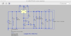
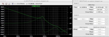
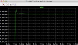
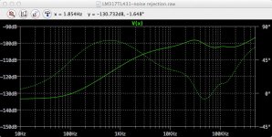
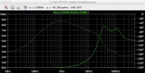
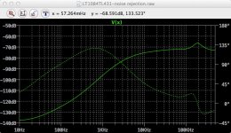
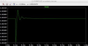
I finally finished all the modelling for the LM317+TL431 (actual circuit to use SPX431). Below is the circuit, loop gain and phase margin analysis, transient response, noise rejection and output impedance output from the model.
LTspice files and charts:
https://dl.dropboxusercontent.com/u/70685392/Electronics/LM317TL431 latest/LM317TL431-stability.zip
LTspice files and charts:
https://dl.dropboxusercontent.com/u/70685392/Electronics/LM317TL431 latest/LM317TL431-stability.zip
Attachments
Last edited:
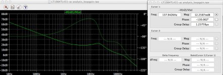
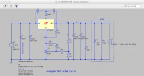
I also looked at replacing the LM317 with a LT1084.
I examined the impact of changes to R5, R6 and C2 on loop gain and phase margin, transient response and noise rejection.
An increase in R5:
- improves phase margin, worsens PSRR, worsens transient response
An increase in R6:
- worsens phase margin, worsens PSRR, improves transient response
An increase in C2:
- marginally improves phase margin, worsens PSRR, improves transient response
Phase margin is very sensitive to R5 and R6. Transient response is more sensitive to C2.
I finally settled on leaving R5 the same and optimising each of R6 and C2.
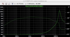
Below is the circuit, loop gain and phase margin analysis, transient response, noise rejection and output impedance output from the model.
LTspice models and charts
https://dl.dropboxusercontent.com/u.../LT1084TL431 latest/LT1084TL431-stability.zip
I examined the impact of changes to R5, R6 and C2 on loop gain and phase margin, transient response and noise rejection.
An increase in R5:
- improves phase margin, worsens PSRR, worsens transient response
An increase in R6:
- worsens phase margin, worsens PSRR, improves transient response
An increase in C2:
- marginally improves phase margin, worsens PSRR, improves transient response
Phase margin is very sensitive to R5 and R6. Transient response is more sensitive to C2.
I finally settled on leaving R5 the same and optimising each of R6 and C2.
Below is the circuit, loop gain and phase margin analysis, transient response, noise rejection and output impedance output from the model.
LTspice models and charts
https://dl.dropboxusercontent.com/u.../LT1084TL431 latest/LT1084TL431-stability.zip
Attachments
Last edited:
I just posted some TL431 measured data that might be of interest to readers of this thread:
http://www.diyaudio.com/forums/powe...ut-voltage-measurement-1-96v.html#post4241788
http://www.diyaudio.com/forums/powe...ut-voltage-measurement-1-96v.html#post4241788
Hello.
Sorry for bumping a really old thread.
But I've got some question in regards to LM317 (and LM337 too) and those circuit presented here (some variations of TL431 as a reference).
And I think it will be better to add a new post than making a new thread and refering here etc.
So let's start.
Does it really worth it? After all there is no simple answer here.
After looking at preamp.org plots it's really hard to see any real benefits between typical circuit (with CAdj added) and good TL431/Zener, after all 1/f noise is not my concern here.
But after all there was more circuits presented here which was not refered and tested by preamp.org owner.
How about replacing TL431 (even those that are mentioned here as a good) with LM329 or something else? Just to play, we are not talking about cost/solution size.
Few pages back there was a speech about BFC, placing a capacitors to compensate TL431 etc. does it really worth it? Some pictures from this thread are not available.
I'm just thinking about improving LM317 and LM337 performance because I've got plenty of them at home and I see them widely used in many circuits (for audio), so it might be worth it.
TL431 is also cheap and buying some CRD diode as a constant current source is not a big deal.
Another question is, if Tl431 play with output impedance does output inductance will change (vs. load) typical LM317 have rather high output inductance at low load (below 50mA) and it will be rather constant up to 1.5A if we go further than 50-100mA.
I'm asking because it will be important to choice a proper ESR capacitor or series resistor to avoid any resonance.
Anyone here was talking about LM317, but there is almost no talk about LM337 and no measurements of his brother.
So taking this opportunity to ask I just want to know few things.
So if improvements are visible with LM317 will it still be worth implementing with LM337 which is considered as a better IC?
Does any of you got a plot or info about output inductance vs load for typical LM337 circuit (with and without CAdj).
I think that it would be nice to play with both with similiar care and effort.
But most data was taken with LM317 only.
TL431 is a shunt regulator and can sink up to 100mA as a shunt IF cooled well. It is not the same as delivering 100mA.
The combination of TL431+LM317 I do not understand in this context. Even if you can have the precision of the TL431, an audio circuit does normally not need a more precise voltage than what an LM317 can supply. If you combine the two, it appears you more-or-less end up with the noise of the LM317.
You can also use the TL431 alone if you you have a low or steady current consumption of the load. The TL431 can provide a very fast regulation and probably more precise than the LM317.
Last edited:
There are two different power-supply needs for audio use.
Power amplifiers need a power supply that can supply the right voltage and current (trivial) AND is able to provide a regulation that maintains the voltage as constant as possible when the current varies heavily and fast. On top of that, the hum has to be under control.
Pre-amplifiers, audio Bluetooth modules etc. have generally a rather low and constant current consumption. The exact voltages are not important (+/- 5% can be tolerated) and the dynamic behavior is not a major concern either. What is important is noise and hum. Noise has only to be reasonable as the PSRR of the load circuit will provide further damping. Hum is important because it will spread on the ground conductor.
Therefore, a well designed (hum-wise) power supply using LM317/LM337 is normally fully sufficient for pre-amplifiers etc. You can design more sophisticated power supplies but you will hardly hear the difference (for solid state).
The TL431 can be used for better performance than an LM317. But, as the TL431 is a shunt regulator, it is inconvenient unless the load current is very constant. Or, if very low noise is essential.
The TL431 shunt regulator can be combined with the LM317 serial regulator by replacing the LM317 circuit resistor going to ground with the TL431 cathode and anode and use the TL431 control pin as feed-back pin.
LM317 is already rather fast in regulating but the combination may be even faster. This is not really important for a rather constant load consumption. The TL431 will no doubt have less drift which again is not important for this application. Last, the TL431 may result in better low-frequency regulation (noise) in the audio band which is not really needed taking account of the already rather good performance of the LM317.
The combination of the TL431 and LM317 can be very useful for other applications such as measuring circuits. For low-power audio, I see no real gain simply because the better performance, that can be measured, is hardly to be heard.
Last edited:
I've done some testing on a real world scenario and here is the data. Note dB levels are totally relative.
Quick conclusion - LM317 using resistors and a capacitor to bypass the adjust pin is best.
My test circuit is an active crossover with a bluetooth receiver and power-amp onboard. The bluetooth receiver draws current in nasty HF gulps and dumps it back to ground. These currents get in to the audio signal through any signal to ground connections in the crossover. My audio signals actually use a virtual ground so the op-amps can run on a single supply. This means the quality of the regulator feeding the V-GND directly affects noise feed through from the BT receiver. The output is fed to the power amplifier which must connect to 'real' ground so I guess that is where the stuff around 1KHz gets in regardless of the regulator under test.
So as a first reference, here is the op-amps and V-GND fed from the +15V rail with no dedicated regulator (although the BT receiver has it's own regulator).
Secondly we can try the LM317 as below.
Next we can try replacing the adjust resistor with a zener diode.
Now we bypass the zener with 10uF Pan FC.
Okay lets try the TL431. This is a part from on-semi I tried the following conficurations but they were clearly unstable with lots of HF ossilation so I didn't keep it switched on for testing.
This one was stable.
I tried bypassing the ressitor with 15uF tant.
Finally I tried the configuration shown by SGK in post #169
I also tried the same with a TI TL431 (supposed to be a lot more noisy).
Finally here is a zoomed in overlay.
Quick conclusion - LM317 using resistors and a capacitor to bypass the adjust pin is best.
My test circuit is an active crossover with a bluetooth receiver and power-amp onboard. The bluetooth receiver draws current in nasty HF gulps and dumps it back to ground. These currents get in to the audio signal through any signal to ground connections in the crossover. My audio signals actually use a virtual ground so the op-amps can run on a single supply. This means the quality of the regulator feeding the V-GND directly affects noise feed through from the BT receiver. The output is fed to the power amplifier which must connect to 'real' ground so I guess that is where the stuff around 1KHz gets in regardless of the regulator under test.
So as a first reference, here is the op-amps and V-GND fed from the +15V rail with no dedicated regulator (although the BT receiver has it's own regulator).
An externally hosted image should be here but it was not working when we last tested it.
Secondly we can try the LM317 as below.
An externally hosted image should be here but it was not working when we last tested it.
Next we can try replacing the adjust resistor with a zener diode.
An externally hosted image should be here but it was not working when we last tested it.
Now we bypass the zener with 10uF Pan FC.
An externally hosted image should be here but it was not working when we last tested it.
Okay lets try the TL431. This is a part from on-semi I tried the following conficurations but they were clearly unstable with lots of HF ossilation so I didn't keep it switched on for testing.
An externally hosted image should be here but it was not working when we last tested it.
This one was stable.
An externally hosted image should be here but it was not working when we last tested it.
I tried bypassing the ressitor with 15uF tant.
An externally hosted image should be here but it was not working when we last tested it.
Finally I tried the configuration shown by SGK in post #169
An externally hosted image should be here but it was not working when we last tested it.
I also tried the same with a TI TL431 (supposed to be a lot more noisy).
An externally hosted image should be here but it was not working when we last tested it.
Finally here is a zoomed in overlay.
An externally hosted image should be here but it was not working when we last tested it.
Last edited:
Bookmarked!
Really good and thorough work.
I would have assumed TL431 could provide some improvement of the LM317 performance, but no. Keep it simple as suggested in the LM317 datasheet.
The only combination you did not try was the TL431 feedback version (unstable) with the 15uF across the TL431.
Very useful results.
From the basic use of LM317, improvements deal with replacing the resistor from the Adj pin to ground.The combination of the TL431 and LM317 can be very useful for other applications such as measuring circuits. For low-power audio, I see no real gain simply because the better performance, that can be measured, is hardly to be heard.
The goal being better regulation and less noise ( hum and hiss ? )
First improvement: A capacitor across the resistor.
Second improvement: No cap, a zener diode instead of the resistor.
Third improvement: A TL431 instead of the zener.
This seems to me the ideal solution because of the TL431: 0.2 ohm dynamic impedance.
I do not understand a controversy in this thread: Isn't it clear that using a TL431 is better than a zener diode in this design. I must have missed something; What is the reason ?
Unfortunately, I cannot open the images in post 177.
Last edited:
- Status
- This old topic is closed. If you want to reopen this topic, contact a moderator using the "Report Post" button.
- Home
- Amplifiers
- Power Supplies
- LM317+TL431, really?