Re: Are You Experienced? ;-)
just wanted to add that the adj pin pushes out the current, not draws the current. I agree with the rest of your comments.
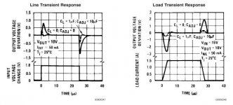
Anyway, here is what engineers at National have to say about ripple rejection and load regulation, with and without that 10uf cap.
Elso Kwak said:The adjustment terminal draws very little current (50-100µA),
just wanted to add that the adj pin pushes out the current, not draws the current. I agree with the rest of your comments.
Anyway, here is what engineers at National have to say about ripple rejection and load regulation, with and without that 10uf cap.
Attachments
Re: Shall I proceed to PCB this circuit, then?
Maybe you should add a capacitor between ADJ and ground but this is dependant of your load. 4700 uF at the out is much, much more than you need.
I think the design is rather OK but why do you need soft start?tcpip said:I did a PCB layout. Does it look okay? It appears that you're all in agreement that the circuit does not have fundamental flaws, it just doesn't work the way the book explained. On the whole, soft start is a good thing anyway, so no harm done anywhere, I guess.
Maybe you should add a capacitor between ADJ and ground but this is dependant of your load. 4700 uF at the out is much, much more than you need.
Hi Kwak!
... I agree on the comment of Horrowitz that also a standard
3-pin voltage regulator can be used like a floating LM317.
The traditional 7805 can also deliver 15V this way.
From my experience the regulation of this circuitry never
caused issues (but also a 1uF cap from output to ground required
in order to prevent ringing), even if it is poor compared to LM317.
But the limited input voltage capability of the 7805 can easily
run someone into trouble.....
7905 for neagtive supplies runs fine this way, too. But it is more critical in ringing. And be careful 7905 has a different pinning than 7805.
If it is connected wrong (when expecting the pinning as in 7805),
it showed a spectacular dead. The plastic of the enclosure
splattered through the whole room. ...luckily not shooting into my eyes...
Another point which I am missing in these rgeulators.
7805 does NOT have internal protection diodes:
- output to input: protection against sourcing loads...
- output to ground: protection if a short circuit happens
between the two outputs of a positive regulator and a negative
regulator. One of both will be stronger and pull the other one
beyond ground, if not diode is there...
deja vu with no end in sight
"After 100 confusing posts may I quote from Horowitz"
You may....... What page was it was it when I suugested reading the data sheet which explains the observations by Howorwitz in even more detail.
"engineers at National did spend sometime on this "incorrectly implemented" circuit"
Which particular circuit are we talking about now? I believe the original questions on implementation concerned whether the circuit composed of the emitter follower and RC circuit connected to the base improves the regulation of the regulator circuit as Mr. Sloan is said to have claimed or is just a slow start circuit (which indeed does function as a slow start circuit) as outlined in the data sheet. No one's competence (well ... no engineers at any rate) has been called into question by me. The Spice models are posted, the circuit is posted, and the way the regulator functions has been explained very well in the data sheets and maybe less well in the thread.
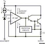
Once again, I post a block diagram of the basic regulator topology to end speculation on that topic. This ap note is well worth reading as well.
From: http://www.national.com/an/AN/AN-181.pdf
"After 100 confusing posts may I quote from Horowitz"
You may....... What page was it was it when I suugested reading the data sheet which explains the observations by Howorwitz in even more detail.
"engineers at National did spend sometime on this "incorrectly implemented" circuit"
Which particular circuit are we talking about now? I believe the original questions on implementation concerned whether the circuit composed of the emitter follower and RC circuit connected to the base improves the regulation of the regulator circuit as Mr. Sloan is said to have claimed or is just a slow start circuit (which indeed does function as a slow start circuit) as outlined in the data sheet. No one's competence (well ... no engineers at any rate) has been called into question by me. The Spice models are posted, the circuit is posted, and the way the regulator functions has been explained very well in the data sheets and maybe less well in the thread.
Once again, I post a block diagram of the basic regulator topology to end speculation on that topic. This ap note is well worth reading as well.
From: http://www.national.com/an/AN/AN-181.pdf
Attachments
Confused?
That was not implied in the quote from Horowitz. Meant was the LM317 without cap at the adjustment terminal.
If you compare the datasheets ofthe 7815 and the LM317 wou will see that the LM317 has better specs with adjustment cap.
Limited input voltage of the 7805? My datasheet mentions 35V.
ChocoHolic said:Hi Kwak!
... I agree on the comment of Horrowitz that also a standard
3-pin voltage regulator can be used like a floating LM317.
That was not implied in the quote from Horowitz. Meant was the LM317 without cap at the adjustment terminal.
For clarity I left the diodes out of the discussion.The traditional 7805 can also deliver 15V this way.
From my experience the regulation of this circuitry never
caused issues (but also a 1uF cap from output to ground required
in order to prevent ringing), even if it is poor compared to LM317.
But the limited input voltage capability of the 7805 can easily
run someone into trouble.....
7905 for neagtive supplies runs fine this way, too. But it is more critical in ringing. And be careful 7905 has a different pinning than 7805.
If it is connected wrong (when expecting the pinning as in 7805),
it showed a spectacular dead. The plastic of the enclosure
splattered through the whole room. ...luckily not shooting into my eyes...
Another point which I am missing in these rgeulators.
7805 does NOT have internal protection diodes:
- output to input: protection against sourcing loads...
- output to ground: protection if a short circuit happens
between the two outputs of a positive regulator and a negative
regulator. One of both will be stronger and pull the other one
beyond ground, if not diode is there...
If you compare the datasheets ofthe 7815 and the LM317 wou will see that the LM317 has better specs with adjustment cap.
Limited input voltage of the 7805? My datasheet mentions 35V.
At the end of the tunnel is light, resurrection or dead?
Hi Fred,
It is a long dark tunnel........
Funny thing is that the LM317 datasheet is at the end of Horowitz in my second edition, page 1086, Appendix K.")
Fred Dieckmann said:"After 100 confusing posts may I quote from Horowitz"
You may....... What page was it was it when I suugested reading the data sheet which explains the observations by Howorwitz in even more detail.
"engineers at National did spend sometime on this "incorrectly implemented" circuit"
Hi Fred,
It is a long dark tunnel........
Funny thing is that the LM317 datasheet is at the end of Horowitz in my second edition, page 1086, Appendix K.
35V for 7805?
Uhps, somewhen I learned this rule of thumb:
78XX series has a max input voltage of
nominal output voltage plus 15V..., but this was not from data
sheets....
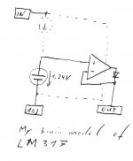
And the picture might help to explain my simplified understanding of
the LM317. I don't care where they run their idle currents as long
as they manage to keep it low.....
Not a nice picture, but it was faster than with ORCAD.
Uhps, somewhen I learned this rule of thumb:
78XX series has a max input voltage of
nominal output voltage plus 15V..., but this was not from data
sheets....
And the picture might help to explain my simplified understanding of
the LM317. I don't care where they run their idle currents as long
as they manage to keep it low.....
Not a nice picture, but it was faster than with ORCAD.
Attachments
I cannot believe it!
Wow, 180 degree turn around,. Sounds like you are in strong, no complete, disagreement with the person who said the following:
"Not a soft start circuit", "implementation is wrong". Sounds like pretty incompetent to me.
Fred Dieckmann said:is just a slow start circuit (which indeed does function as a slow start circuit) as outlined in the data sheet. No one's competence (well ... no engineers at any rate) has been called into question by me.
Wow, 180 degree turn around,
. Sounds like you are in strong, no complete, disagreement with the person who said the following:It is not a soft start circuit, which is more easily achieved by putting a cap across the resistor from the adjustment terminal to ground. The concept of the circuit is fine but the implementation is wrong.
"Not a soft start circuit", "implementation is wrong". Sounds like pretty incompetent to me.
Fred Dieckmann said:I am even looking at another improment to the regulator circuit with a simple active current source between Vout and ADJ......
Fred
Rather than a current source between Vout and ADJ, would it not be easier/better (given the voltage restraint within which the current source must work) to utilise a voltage reference (Zener/TL431/???, with a capacitor bypass) between ADJ and Ground?
Geoff
pinkmouse said:Guys, can we keep this discussion on a practical
Hi,
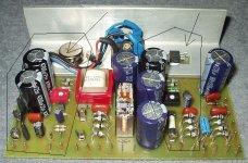
I was building this soft start regulator with LM338 (12.6V/3A) and LT1085 (6.3V/1A) for tubes heating supply (6C33, 6SN7,6J5) in my new tube amp (not finished yet). Soft start circuit works.
With 100k/10uF release time is around 2-3 sec. Just what I need.
Regards
Attachments
ChocoHolic said:you also turned your mind 180°. in the beginning
you claimed that fred is an excellent expert!
How wrong I was,
.Yeah. There got to be something Fred is good at.
moamps said:Soft start circuit works.
Regards
Thanks, moamps. It is the 2nd real life confirmation that the engineers at National didn't implemented it wrong, contrary to some expert's view.
Not that I know exactly what Fred is suggesting with the CCS and
I am not clear if Geoff suggests only replacing one of the resistors
with a zener, however, using a CCS and a Zener in combination
has been suggested earlier:
http://www.diyaudio.com/forums/showthread.php?postid=36168#post36168
I think this design has been discussed also in some even earlier
thread that I couldn't find right now, and I get the impression of
the author of the linked post found it in some earlier discussion.
Pedja said:And as I said, there was certain difference in sound with and without it. Does anyone know why?
I would venture a guess on the lm317.
it seems to me that its transient response isn't too good, from the datasheet. so during peaks, its output may go down too much, vs. using a straight capacitor.
Not sure tho. if that is what contributed to your sound differences.
- Status
- This old topic is closed. If you want to reopen this topic, contact a moderator using the "Report Post" button.
- Home
- Amplifiers
- Solid State
- LM317-based regulated PSU: how does this thing work?