Re: Spice output
Great looking chart Fred you have there.
Pity that they aren't for the right circuit,")
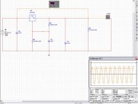
Fred Dieckmann said:The output of my simulation below:
Great looking chart Fred you have there.
Pity that they aren't for the right circuit,
Talk is cheap.........
"But before you do all that, please make absolutely sure that you are simulating the National circuit, not your truly incorrectly implemented one. Pleeeeeeeeeese!"
Post the text file for you regulator model then. Capacitor bypass gave results similar to what was expected from the data sheet. I have given very explict information on data sheets, Spice models, and circuit descriptions. It seems to me that the burden of proof is in your court for you assertions. I would really like to get on to circuits that will increase the regulator's performance and will anyway if we can't get past this impass. I would think others would as well.
Twisting in the wind
Use my model and see if you get the same result. The circuit is from the one in question from the first entry in the thread. Like I said....
the burden of proof is in your court. If this is not the circuit you are talking about post the one you are refering to. I will not only look at my work but will let others so they can tell me if they get similar results.
All I seem to be hearing is excuses and not much circuit detail.........
Of course I expect to see some more.
Attachments
What circuit are we talking about
R7 is 47K and corresponds to R5 IN THE CIRCUIT IN THE FIRST POST OF THIS THREAD........ YOU KNOW..... THE CIRCUIT THAT THIS WHOLE THREAD WAS ABOUT.
If we are now talking about a different circuit let me know what it is please. This thread is one again drifting away from the technical issues
into nonsense and I will keep dragging it back as long as it takes....
A model for the LM 317 that came with the Micro Cap 7 demo Spice program. I have note tried it yet but I will later.
It appears to be the same as the TI model posted earlier.
*LM317 Adjustable Voltage Regulator
*Adjustable Voltage Regulator pkg:TO-220 3,1,2
*Connections:
* Input
* | Adjust
* | | Output
* | | |
.SUBCKT LM317 1 2 3
J1 1 3 4 JN
Q2 5 5 6 QPL .1
Q3 5 8 9 QNL .2
Q4 8 5 7 QPL .1
Q5 81 8 3 QNL .2
Q6 3 81 10 QPL .2
Q7 12 81 13 QNL .2
Q8 10 5 11 QPL .2
Q9 14 12 10 QPL .2
Q10 16 5 17 QPL .2
Q11 16 14 15 QNL .2
Q12 3 20 16 QPL .2
Q13 1 19 20 QNL .2
Q14 19 5 18 QPL .2
Q15 3 21 19 QPL .2
Q16 21 22 16 QPL .2
Q17 21 3 24 QNL .2
Q18 22 22 16 QPL .2
Q19 22 3 241 QNL 2
Q20 3 25 16 QPL .2
Q21 25 26 3 QNL .2
Q22A 35 35 1 QPL 2
Q22B 16 35 1 QPL 2
Q23 35 16 30 QNL 2
Q24A 27 40 29 QNL .2
Q24B 27 40 28 QNL .2
Q25 1 31 41 QNL 5
Q26 1 41 32 QNL 50
D1 3 4 DZ
D2 33 1 DZ
D3 29 34 DZ
R1 1 6 310
R2 1 7 310
R3 1 11 190
R4 1 17 82
R5 1 18 5.6K
R6 4 8 100K
R7 8 81 130
R8 10 12 12.4K
R9 9 3 180
R10 13 3 4.1K
R11 14 3 5.8K
R12 15 3 72
R13 20 3 5.1K
R14 2 24 12K
R15 24 241 2.4K
R16 16 25 6.7K
R17 16 40 12K
R18 30 41 130
R19 16 31 370
R20 26 27 13K
R21 27 40 400
R22 3 41 160
R23 33 34 18K
R24 28 29 160
R25 28 32 3
R26 32 3 .1
C1 21 3 30PF
C2 21 2 30PF
C3 25 26 5PF
CBS1 5 3 2PF
CBS2 35 3 1PF
CBS3 22 3 1PF
.MODEL JN NJF(BETA=1E-4 VTO=-7)
.MODEL DZ D(BV=6.3)
.MODEL QNL NPN(EG=1.22 BF=80 RB=100 CCS=1.5PF TF=.3NS TR=6NS CJE=2PF
+ CJC=1PF VAF=100)
.MODEL QPL PNP(BF=40 RB=20 TF=.6NS TR=10NS CJE=1.5PF CJC=1PF VAF=50)
.ENDS LM317
http://www.spectrum-soft.com/demoform.shtm
Results with 10uF ADJ cap bypass. The model is the same as the one show earlier with slow start circuit replaced with circuit with cap across 2.4K resistor. The two regulator circuits are identical except for cap. rejection went from 56dB to 73dB at 120 Hz
Attachments
Yes Fred. Nobody refutes the fact that a cap from ADJ to ground improves ripple. The question - as originally stated - was if Slones circuit improved ripple rejection further, in addition to being a slow start circuit.
So, pray tell, how is R5 in the original circuit connected? And how is your R7 connected? Is there a faint chance they might differ?
I just want you to run a simulation on the same circuit as Millwood, but you'll have to actually look at the circuits!
Rune
So, pray tell, how is R5 in the original circuit connected? And how is your R7 connected? Is there a faint chance they might differ?
I just want you to run a simulation on the same circuit as Millwood, but you'll have to actually look at the circuits!
Rune
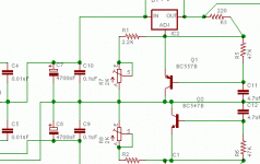
R7 connected to ADJ instead of Vout
If you guys would stop being cryptic and say what the difference is.
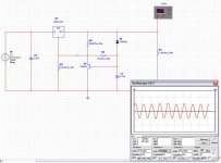
Moving R7 to ADJ where it should be gives a about a 0.4dB difference due to the 47K impeadance being in parallel with the 2.4K resistor as the capacitor impedance decreases with frequency. The transistor is turned off in either circuit version and it offers no improvment as a follower. You would be better off putting the cap across the 2.4 K resistor if you were look to improve the perfomance of the regulator.
If you guys would stop being cryptic and say what the difference is.
Moving R7 to ADJ where it should be gives a about a 0.4dB difference due to the 47K impeadance being in parallel with the 2.4K resistor as the capacitor impedance decreases with frequency. The transistor is turned off in either circuit version and it offers no improvment as a follower. You would be better off putting the cap across the 2.4 K resistor if you were look to improve the perfomance of the regulator.
Attachments
Thanx Fred. Took you a while, there. I'd be a bit wary of telling people to read the data sheets if I were you
Now you've confirmed what many of us have believed, which is that the soft start circuit affects ripple rejection marginally.
I guess the burden now falls on Millwood to present a plausible explanation to the improvements he has simulated.
I'm off to bed now, long overdue
Rune
Now you've confirmed what many of us have believed, which is that the soft start circuit affects ripple rejection marginally.
I guess the burden now falls on Millwood to present a plausible explanation to the improvements he has simulated.
I'm off to bed now, long overdue
Rune
Re: Re: Thanks for the sim! This is great!
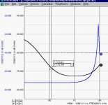
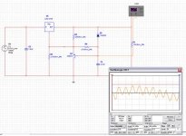
now, here is a new chart. I put the ground probe on the emitter of the bjt and the B channel probe on the base of the emitter. so now B channel shows the be junction voltage.
it is about 4mvpp.
so Steven is right: at steady state, the BJT is essentially take out of the circuit and it will not impact ripple rejection.
My prior (substantial) improvement was due to reading the wrong ripple (on the base of the bjt). sorry for the mistake.
millwood said:On Steven's question, I didn't look at the steady state to see to what extent the transistor is conducting (i tend to agree with you there). I will poke around more tonight.
now, here is a new chart. I put the ground probe on the emitter of the bjt and the B channel probe on the base of the emitter. so now B channel shows the be junction voltage.
it is about 4mvpp.
so Steven is right: at steady state, the BJT is essentially take out of the circuit and it will not impact ripple rejection.
My prior (substantial) improvement was due to reading the wrong ripple (on the base of the bjt). sorry for the mistake.
Attachments
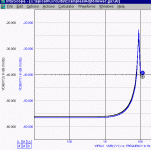
millwood said:without Cadj: 4mvpp
with a 10uf Cadj: 0.4mvpp
the soft start circuit: 25uvpp
so this table should really read:
without Cadj: 4mvpp
with a 10uf Cadj: 0.4mvpp
the soft start circuit: 4mvpp
Does anyone have any doubt about if the soft start circuit is incorrectly implemented?
Normally, in most adjustable 3-terminal regulator data sheets, the manufacturer will suggest using a 10uF cap on the Adj pin for improved supply voltage (ripple) rejection.
I located an interesting paper on the effects of the CAdj capacitance and LM317 regulator stability <http://www.aeng.com/pdf/regulator.pdf>.
Nonetheless I would like to know if anyone here has experimented with very much smaller-than-normal capacitances for CAdj, or for that matter, very much larger-than-recommended capacitances. Measurements, simulations and subjective experiences all welcome.
TIA, jonathan carr
Jonathan,
It is not even close to the comprehensive answer on your question, but still might tell something. Note that it is about LM338 and not LM317 (which, I guess, would be less sensitive in that regard).
http://users.verat.net/~pedjarogic/audio/gainclone/lm338.htm
Pedja
It is not even close to the comprehensive answer on your question, but still might tell something. Note that it is about LM338 and not LM317 (which, I guess, would be less sensitive in that regard).
http://users.verat.net/~pedjarogic/audio/gainclone/lm338.htm
Pedja
To cap or not to cap?
Sorry to be a little slow on the uptake, but now that Millwood has restated his sim results and you've all discussed the Cadj question a bit, I was curious to know... should we keep the cap or not?
Also, I was wondering what happens to the voltage drop across C11 when there's a ripple (caused by a sudden change of Rload of the regulated supply) on the output supply rails? Mind you, I'm not talking about a ripple in the input to the circuit, but a sudden change of load impedance in the output of the circuit. I know nothing about simulators, etc, but I was wondering whether any of your simulations has tried checking this? Since the Zout of the LM317 is not actually zero, I'm sure there will be a bit of a ripple in the output rail, won't there? Will this momentarily change the voltage drop across C11?
C11 is the 4.7uF cap across collector-base of the transistor.
In case my question is incredibly naive and stupid (likely), please can you just limit yourself to, say, 20 words while saying so? Please? That would be nice.
I think we all agree now that you should keep Cadj, and that it will improve both line and load regulation. Simulations bear this out, and it is in accordance with the data sheet. Millwood posted the relevant graph a couple of pages ago Load regulation.
To keep or not to keep the soft start circuit is a different issue. It does nothing (OK, very little) for regulation and adds to complexity. It is probably not a good idea for an adjustable supply, as it will mean raising the voltage will "soft started", which might not be what you want.
Rune
To keep or not to keep the soft start circuit is a different issue. It does nothing (OK, very little) for regulation and adds to complexity. It is probably not a good idea for an adjustable supply, as it will mean raising the voltage will "soft started", which might not be what you want.
Rune
- Status
- This old topic is closed. If you want to reopen this topic, contact a moderator using the "Report Post" button.
- Home
- Amplifiers
- Solid State
- LM317-based regulated PSU: how does this thing work?