Cool thanks for that FlipC
I was taking a look at your old TH-mini clone values for Hornresp.
It shows the driver ~1/2 way out of the mouth, which would change your predictions a little much.
I have never seen an actual TH-mini so I can't really tell if the horn has that last separation. Your compression ratio was also 4.5 to 1 which seems a bit high to me.
Did you change your Hornresp model.
Don't know if you saw this one I built.
http://www.diyaudio.com/forums/showthread.php?postid=1584978#post1584978
I originally played with akabak trying to model all of the discrete segments, junctions and bens before people simplified the akabak tapped horn process. Some where earlier on the forum are my initial AKABAK numbers and graphs.
Your horn path appears to be significantly longer than I expected. Do you have any sweeps?? I'd like to try and model your tapped horn, did you post the dimensions.
The one thing that I have been unclear about with my layout is will the effective length of the horn path be cut off.
I was trying to keep the conical expansion a little more constant.
If you really want to build one I'll post the dimensions, but I may be wrong about my layout. Although I did come close to the DTS-20 with my TH layout. - about 2Hz for the low end.
So Far for all of my layouts I've tried to keep the compression ratio 3:1.
Also I'm slightly concerned about the longevity of your driver mounting which seems to have no way of accommodate for the displacement of the surround currently.
Anyhow its all fun stuff. I'm very interested in playing with TH's more.
Antone-
So many questions ..
I really need to get those pics back online...
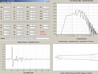
fb - the dips get filled.
My OG posted HR data was just that.
I have a problem with getting out to the garage and doing stuff on paper. I have about 5 sheets here with crap all over them from my minis.
So actual distance from mouth to driver
is about 10-15 cm. 3.5-4" is close.
last seperation?
I assume you mean the last segment in the path? I did that to get the length needed for 1/4 wave of 50Hz. I took the outer dimensions of the TH Mini and the 1/4 of 50 Hz. And folded it to fit within that constraint. (which i just use a straight line to do that)
Well in a normal folded horn
one would keep it to 3:1 but again after reading I came to the conclusion that it can be higher in a TH. Which I think plays a part into the SPL #'s DSL reports. That is just an assumption though.
Also to note on this is that the 2 I actually built the driver fires 100% into the first segment. So no where near the same. Though on the next 2 i will build them to spec. So that I can compare the 2.
As far as the driver baffle goes. That Sketchup model was done just to show you the layout. That baffle is wrong in location and I would actually router the cone area enough for clearance though.
-Side note: On the Labs I have to have a seperate baffle to handle the 13+ MM excursion.
In regards to the DTS esk clone.
Yes I have at least seen the pic of it in the shop. Like the one's over at speakerstore.nl and volvo's. I will assume that is 88" tall?
I really need to get those pics back online...
fb - the dips get filled.
My OG posted HR data was just that.
I have a problem with getting out to the garage and doing stuff on paper. I have about 5 sheets here with crap all over them from my minis.
So actual distance from mouth to driver
is about 10-15 cm. 3.5-4" is close.
last seperation?
I assume you mean the last segment in the path? I did that to get the length needed for 1/4 wave of 50Hz. I took the outer dimensions of the TH Mini and the 1/4 of 50 Hz. And folded it to fit within that constraint. (which i just use a straight line to do that)
Well in a normal folded horn
one would keep it to 3:1 but again after reading I came to the conclusion that it can be higher in a TH. Which I think plays a part into the SPL #'s DSL reports. That is just an assumption though.
Also to note on this is that the 2 I actually built the driver fires 100% into the first segment. So no where near the same. Though on the next 2 i will build them to spec. So that I can compare the 2.
As far as the driver baffle goes. That Sketchup model was done just to show you the layout. That baffle is wrong in location and I would actually router the cone area enough for clearance though.
-Side note: On the Labs I have to have a seperate baffle to handle the 13+ MM excursion.
In regards to the DTS esk clone.
Yes I have at least seen the pic of it in the shop. Like the one's over at speakerstore.nl and volvo's. I will assume that is 88" tall?
For high compression ratio you have to make sure the cone of the driver is up to it or it will shred after a while.
These are the AKABAK values I think you posted a while ago.
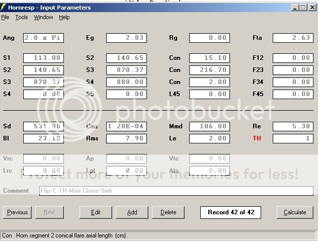
Look at where it places the driver in your schematic.
I think most tapped horns end up needing to be a little bit greater than 1/4 Wave length to achieve desired performance. They fall a little short if you make them spot on 1/4 wave.
Your path is obviously a little longer than mine and I think mine falls a little short of 1/4 wave to the center of the horn mouth. I don't know if the last wall can be considered part of the path length.
Antone-
These are the AKABAK values I think you posted a while ago.
Look at where it places the driver in your schematic.
I think most tapped horns end up needing to be a little bit greater than 1/4 Wave length to achieve desired performance. They fall a little short if you make them spot on 1/4 wave.
Your path is obviously a little longer than mine and I think mine falls a little short of 1/4 wave to the center of the horn mouth. I don't know if the last wall can be considered part of the path length.
Antone-
Hmm or maybe not I just looked at Flips path length from the above Hornresp values.
He's got 1/4 wave path of 49.1Hz
I looked at the one I linked to and it has 1/4 wave path length of 88Hz.
So I guess path length isn't so critical according to the Hornresp model.
I think part of it is the volume or equivalent air mass.
I still don't know if my layout is reasonable. The angles are harder to cut than FlipC's but there are a few less cuts.
I guess I should buy some MDF and a driver and see whats what.
Antone-
12PS100 Dual for FlipC
Hi FlipC,
Thanks for the additional information and pictures.
I'm attaching the Hornresp model and the drawings for a Dual 12" box using the B&C 12PS100. I tried to design the horn into a fixed 23-7/8" x 48" x 15" box for easier wood cutting, and better wood use. I also tried to keep the funny angles, and little support pieces to a minimum. It turned out to be a bit more difficult than I thought it would be, and the details for the driver mounting will have to be worked out with the drivers in hand, e.g.: final sizes of driver mounting plates and support pieces.
Let me know what you think.
Regards,
Attachments
tb46
how are you going to accomplish your desired compression, on your Dual 12 TH.
I'm not sure if your planning on making a Karlson Coupler style slot in front of one of them. But I'm pretty sure you want even loading on both of your drivers. Which looks unlikely in that layout.
I don't think that Horn Resp is really capable of accurately modeling what you are proposing to build. You may be able to come closer with AKABAK.
Post #649
Hi sumsound,
You are correct, Hornresp does not provide for the complete modeling of this enclosure, but it provides for exporting of the Hornresp model into AkAbak. At the low frequencies involved the distance from driver to driver is so small, that they basically work as one. That fact allows Hornresp to be used for modeling. You will have noticed, that the S2 and S4 points are half-way between the drivers. I believe that the model is just as accurate as the model that has been used successfully for the THSpud, which has a similar driver arrangement. I reduced the S1 area over the one used in the THSpud, but it would make sense to make the filler block removable (the one that closes off the lower part of the S1 to S2 section of the horn). That way one can experiment") .
.
Please see:
http://www.diyaudio.com/forums/showthread.php?threadid=134369
There is no need to reduce the entries of the driver outputs into the horn. The cross-section of the horn provides for the necessary compression and coupling. It would be interesting to investigate that subject in depth; e.g.: introducing throat chambers between the driver diaphragms and the horn. This could be done in AkAbak. The resulting models would then have to be build and measured. The concept of removable mounting plates provides for just that. There has been some modeling done in the "Collaborative Tapped Horn" thread. It was around the same time when Cordraconis posted his "AkAbak Th's for Dummies", Post #1187 (and, should he read this: thanks again).
Regards,
Hi sumsound,
You are correct, Hornresp does not provide for the complete modeling of this enclosure, but it provides for exporting of the Hornresp model into AkAbak. At the low frequencies involved the distance from driver to driver is so small, that they basically work as one. That fact allows Hornresp to be used for modeling. You will have noticed, that the S2 and S4 points are half-way between the drivers. I believe that the model is just as accurate as the model that has been used successfully for the THSpud, which has a similar driver arrangement. I reduced the S1 area over the one used in the THSpud, but it would make sense to make the filler block removable (the one that closes off the lower part of the S1 to S2 section of the horn). That way one can experiment
. Please see:
http://www.diyaudio.com/forums/showthread.php?threadid=134369
There is no need to reduce the entries of the driver outputs into the horn. The cross-section of the horn provides for the necessary compression and coupling. It would be interesting to investigate that subject in depth; e.g.: introducing throat chambers between the driver diaphragms and the horn. This could be done in AkAbak. The resulting models would then have to be build and measured. The concept of removable mounting plates provides for just that. There has been some modeling done in the "Collaborative Tapped Horn" thread. It was around the same time when Cordraconis posted his "AkAbak Th's for Dummies", Post #1187 (and, should he read this: thanks again).
Regards,
Attachments
Hi sumsound,
Hornresp takes care of the driver related changes for multiple drivers. The individual horn sections are so short, that the best you can do is get somewhere close. I draw the section height v. path length, and then measure (using ACAD dimensioning tool) the section heigt at the path length to e.g.: a corner, or other point of interest.
Regards,
OK
Weekend is gone and I am back. Just caught up on things.
tb46
I will start modeling this in Sketchup.
I like the design. After my test box I through out that thought process and was looking at the SPUD layout myself.Give me the week to get this done as I need to finsih off the Mini Clone to boot.
Also on the very first box I built
I made it so I could change the throat relatively easy. Speaker baffle mounted to another one that mounted into box. Cheap OSB box.
I choose final from my ear.
Post #654
Hi FlipC,
Time just flies, doesn't it? I agree that it is important to give oneselves as much flexibility as possible in a test box, particularly in the throat area of the tapped horn. As an aside, when you replace the two 12PS100s with four 55-2421s you end up with a similar response, and they actually fit.
Regards,
Hi FlipC,
Time just flies, doesn't it? I agree that it is important to give oneselves as much flexibility as possible in a test box, particularly in the throat area of the tapped horn. As an aside, when you replace the two 12PS100s with four 55-2421s you end up with a similar response, and they actually fit
.Regards,
Re: 12PS100 Dual for FlipC
Hi
What sotware do you use to make these drawings with dimensions and angles? They look like automatically generated thus saving a lot of work.
tb46 said:Hi FlipC,
Thanks for the additional information and pictures.
I'm attaching the Hornresp model and the drawings for a Dual 12" box using the B&C 12PS100. I tried to design the horn into a fixed 23-7/8" x 48" x 15" box for easier wood cutting, and better wood use. I also tried to keep the funny angles, and little support pieces to a minimum. It turned out to be a bit more difficult than I thought it would be, and the details for the driver mounting will have to be worked out with the drivers in hand, e.g.: final sizes of driver mounting plates and support pieces.
Let me know what you think.
Regards,
Hi
What sotware do you use to make these drawings with dimensions and angles? They look like automatically generated thus saving a lot of work.
FlipC TH Mini Clone
Hi FlipC,
refering to your TH Mini Clones (http://www.worldconspiracy.org/speakers/TH-Mini-Clone.png) I have some questions:
What's the slot, which the driver is fireing through, for?
Where have the pics you've posted on the Speakerplans forum been gone?
Is your design similar to a downscaled version of Staipers TH?
greez
Back again -
Post from me will be intermittent due to work schedule.
OK I use Sketchup. Free from Google.
It is pretty easy to use though I don't know how to extract area from a 3D component. Which make things a PITA cause I usually forget something. So if any of you know how. Please do teach.
I need to get Auto CAD and learn that
but I also need to finish other projects outside of my bass addiction...
So I just cut wood to build 2 - 30"x18"x15" reflex cabs for my Lab 12 drivers.
After I get those put together (within a week) I will cut wood to build 2 more of the Mini Clones. (cause I have power left on the amplifier so more BASS)
After that I will build a version of Tb46's dual 12" but will use Eminence Kappa Pro-12A in place of the B&C 12PS100 12" Woofer. 2 of the Kappas will cost me less than 1 of the 12PS and give pretty darn close the same output. Least in a TH.
Also anyone got any good plans for some Dayton 385-88 DVC 15s?"
These came out of my HouseWrecka. Which is sitting in my garage. I might put them back into that and let my wife be pissed about the monstrosity sitting in the living room.
Ibex -
the ones I actually built have no restriction what so ever into the throat. HR called for it but apon testing. I found that it had an effect on overall SPL (power handling) and not sound. I built them to run 2 off of 1 side of a Crown XLS 602. Which isn't enough power to clip them. Least not running a 45 hz filter on them.
As far as the pics you asked about. I migrated web servers back in June
and didn't notice that those disappeared UNTIL a few weeks ago. Which I haven't had time to FIND and re-post.
- Home
- Loudspeakers
- Subwoofers
- Live sound specific Tapped Horn thread...