I have already had a written conversation with Ivan Beaver of DSL regarding the ambiguity of an impedance selectable cabinet not specifically stating the impedance in the sensitivity portion.
He seems to think the specs are fine the way they are written, but there are a lot of us that would like to see that ambiguity cleared up.
The TH-221 spec is in the 2 ohm configuration.
You can tell this by looking at the impedance chart, and also the stated minimum impedance of 2 ohms.
This is also the case with the TH-412, with a nominal impedance of 2 ohm, minimum impedance of 1.6 ohms.
The TH-812 has a nominal impedance of 4 ohm, minimum impedance of 3.5 ohms.
The TH-115 has a nominal impedance of 4 ohm, minimum impedance of 5 ohms.
The specifications just state the voltage applied. The speaker impedance curve determines the power used at any given frequency.
To derive the one watt equivalent sensitivity, you do need to subtract 6 dB from the cabinets rated at 2 ohms, and 3 dB from the cabinets rated at 4 ohms.
Thanx to talking to DSL about the issue. Of course the imp-chart is of the 2 ohm version, I just wasn´t sure if the SPL-Chart was derived from the 2 Ohm Version. This puts everything into perspective and lets me think about max SPL... Looking at the graph, we "only" get about 96dB@20Hz and about 108dB@100Hz. The used speakers must have enormous xmax capability to reach 147dB@100Hz...
AE IB12A: http://www.aespeakers.com/phpbb2/viewtopic.php?f=3&t=1937
$129, I assume discount for multiples but it's not in their webshop yet.
IB12A-4
Fs: 24hz
Qms: 3.8
Vas: 160L
Cms: .4
Mms: 110g
Xmax: 18.5mm
Xmech: 22mm
Sd: 530sqcm
Qes: .38
Re: 2.7ohm
LE: .16mH
Z: 4ohm
Bl: 18.8Tm
Pe: 500W
Qts: .35
1w SPL: 89.6db
2.83V: 94.3dB
$129, I assume discount for multiples but it's not in their webshop yet.
IB12A-4
Fs: 24hz
Qms: 3.8
Vas: 160L
Cms: .4
Mms: 110g
Xmax: 18.5mm
Xmech: 22mm
Sd: 530sqcm
Qes: .38
Re: 2.7ohm
LE: .16mH
Z: 4ohm
Bl: 18.8Tm
Pe: 500W
Qts: .35
1w SPL: 89.6db
2.83V: 94.3dB
Attachments
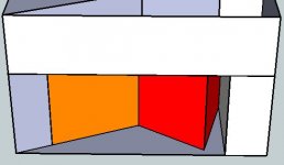
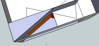
And here's a fold in Sketchup....
Caveats:
I'm hoping for a bit lower extension.
CR is a bit higher than 3:1
Box dimensions chosen to suit some space requirements I have.
The model uses infinitely thin wood.
The expansion between S2 and S3 is different to the HR model.
Speaker drivers are not triangular.
Caveats:
I'm hoping for a bit lower extension.
CR is a bit higher than 3:1
Box dimensions chosen to suit some space requirements I have.
The model uses infinitely thin wood.
The expansion between S2 and S3 is different to the HR model.
Speaker drivers are not triangular.
Attachments
20 downloads, anyone have any comments?
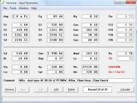
Is Atc input correct in Hornresp? I used JLH's suggestion here: http://www.diyaudio.com/forums/showthread.php?postid=1721788#post1721788, but I'm not sure if that's correct in this situation....
Is Atc input correct in Hornresp? I used JLH's suggestion here: http://www.diyaudio.com/forums/showthread.php?postid=1721788#post1721788, but I'm not sure if that's correct in this situation....
That's an interesting/nice design!
However, I've probably got some problems with interpretating that Sketchup drawing, because it gives me the idea that either Vtc is a bit high (27+ liter) or that it isn't a tapped horn in the picture.
Atc, seems about right (if my interpretation is correct). It shouldn't matter to much, especially if you mask the resonances in HR.
Could you show driver placement?
Best regards Johan
Unless you want to compression load the driver to the filter chamber which in turn loads it at the other end automatically at S2's area, then Atc should always be = at least the driver's Sd and ideally to its cutout area since that's what the filter chamber's Vb is going to 'feel'. This low pass filter chamber serves the same purpose as a BR cab and you wouldn't normally mount the driver's face to the box with a < Sd cutout would you?
GM
GM
Rademakers said:That's an interesting/nice design!
However, I've probably got some problems with interpretating that Sketchup drawing, because it gives me the idea that either Vtc is a bit high (27+ liter) or that it isn't a tapped horn in the picture.
Atc, seems about right (if my interpretation is correct). It shouldn't matter to much, especially if you mask the resonances in HR.
Could you show driver placement?
Best regards Johan
Yeah, Vtc is 27+ liters. It's big to fit the drivers in push-pull. Driver cones are the orange bits, frame+magnet the red bits. The side wall is left off the chamber so you can see inside. The high Vtc works alright in hornresp, so long as Atc is = S2
GM said:Unless you want to compression load the driver to the filter chamber which in turn loads it at the other end automatically at S2's area, then Atc should always be = at least the driver's Sd and ideally to its cutout area since that's what the filter chamber's Vb is going to 'feel'. This low pass filter chamber serves the same purpose as a BR cab and you wouldn't normally mount the driver's face to the box with a < Sd cutout would you?
GM
No.... Have you had a look at the sketchup model? Atc is supposed to be normal to the axis of the horn, but I'm not sure where that is in the odd shaped chamber I've drawn.
Thanks all
Attachments
fb said:
No.... Have you had a look at the sketchup model?
Nope, don't even know which design this is and don't have/use Sketchup or any of the other fancy programs available since I don't have time to learn any of them unless ya'll prefer I not post on the forums for a long time because I'll take the time to learn AkAbak inside out first and it's getting seemingly tougher everyday for this old dog to learn new tricks.
Regardless, Atc is in essence a cutout for the driver in that it's a baffle that has to be at least as big as the cutout if you don't want to compression load Vtc, ergo it's normal to the axis of the driver, so don't really care where it is in relation to the horn unless DB tells us otherwise.
Ditto, it's assumed that the S2 side of the chamber is normal to the axis of the horn, but even if the horn path isn't parallel or perpendicular to Atc, the program doesn't know or care since it's viewed as just a 'X' amount of confined vibrating air mass connecting the two, i.e. its shape means nothing to it since it's an acoustically simple 1D solution.
Anyway, check for yourself what Atc represents, use the TH Wizard to make a chamber to prove that the vertical red line is the Sd's diameter by making Atc somewhat > Sd, than add some Vtc to give it some visible depth and you'll notice that the red line has been extended equally at both ends with black extenders to make the chamber.
BTW, which driver, sim is this? I don't have time to keep up with the threads like I use to.
GM
You're welcome!
I hate to 'rain on your parade', but the driver's published specs lists BL as 18.8 Tm along with a 0.38 Qes which doesn't compute, so assuming Qes is correct since the BL generated one is a ridiculously low 0.13, BL = 10.8 Tm, making your design's response quite a bit different. Hope you haven't burned any wood yet.
Bottom line, best to use the basic T/S specs and let HR calc the rest.
Edit: posted a correction on the AE forum.
GM
GM said:You're welcome!
I hate to 'rain on your parade', but the driver's published specs lists BL as 18.8 Tm along with a 0.38 Qes which doesn't compute, so assuming Qes is correct since the BL generated one is a ridiculously low 0.13, BL = 10.8 Tm, making your design's response quite a bit different. Hope you haven't burned any wood yet.
Bottom line, best to use the basic T/S specs and let HR calc the rest.
Edit: posted a correction on the AE forum.
GM
There goes my free lunch
 Thanks again GM.
I'm well and truly back to the drawing board now.... I'll revisit my AV12 sims....

GM said:You're welcome! OK, I see you changed it to 10.9 Tm.........
GM
Well, like you did, I backcalculated it with WinISD Pro Alpha to 10.86 Tm so I rounded up to 10.9 Tm...
But since it's the same motor it's probably 10.8 Tm like others IB-A...
I will let John double check it, 10.8 Tm or 10.9 Tm won't make a difference anyway considering most T/S parameters move much more than ~1% usually...
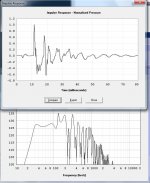
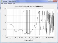
I'm looking at the impulse response of some designs I'm coming up with.... It's atrocious.... but what about within the passband? The attached pic is -3db at 30hz-120hz. The group delay and phase plots look benign in this region as far as I can tell.
What should I be looking for? I don't need super wide bandwidth....
Ta
What should I be looking for? I don't need super wide bandwidth....
Ta
Attachments
- Home
- Loudspeakers
- Subwoofers
- Live sound specific Tapped Horn thread...