Don Snyder said:Easy way to get rid of the two lowest resonances, use structural foam to fill just a little of the corner. It weighs a lot less than all
that plywood!
No parallel walls, no reflection!
In the Furybox, the additional wood weighs under 10 ounces.
2x 4.5" reflectors, diffusers, deflectors whatever we wind up calling them and one 6.5". The wood missing from the sides to make way for the handles and wheels makes up for the top rear and bottom rear panels which also double as deflectors.
I have a ups scale and can actually measure them if you'd like.
If we all come up with a difficult to obtain set of deflectors, foam might make sense for the smaller bits. Removing the rear cuts would also remove the cabinets easy transportability.
If you never plan to run the box above 90hz, you can leave out all the reflectors and cutouts.
Hi Scott - I'm not suggesting a change to your box ... just throwing another possibility into the mix for those who don't
want to make tricky cuts. After all, some of our readers would think that the handle/wheel 45's were beyond them, much less
the 12 degree cut on the flares.
I don't think the Furybox is a good "first project" ... LOL
But it's one Hell of a Tapped Horn!
want to make tricky cuts. After all, some of our readers would think that the handle/wheel 45's were beyond them, much less
the 12 degree cut on the flares.
I don't think the Furybox is a good "first project" ... LOL
But it's one Hell of a Tapped Horn!
FurySub_2009: model v. measurement
Hi Y'all,
I have been trying to find a way to come up with a model that reflects screamerusa's measurements, but I have not been successful.
I'll enclose an AkAbak script that changes the S3 area with the preceding 90 degree bend into S3a, an acoustic mass and S3b (with the respective changes to the length of L23 and L34). I also modelled the throat chamber and duct into the horn. This should be closer too reality, but it doesn't seem to be.
screamerusa: Did you have a chance to measure the FurySub in a free field environment at 10 meters yet? Also, I am using the 4015LF in my models, is that the correct current driver?
Anyhow, this is all quite interesting, isn't it?
Regards,
--------------------------------
|DATA EXPORTED FROM HORNRESP - RESONANCES NOT MASKED
|COMMENT: TH_Eminence_Definimax 4015LF_screamerusa_from dwg
|This is the first attempt to add an acoustic mass centered between S3a and S3b (90degree bend).
|========================================================================================================
|REQUIRED AKABAK SETTINGS:
|File > Preferences > Physical system constants:
|Sound velocity c = 344m/s
|Medium density rho = 1.205kg/m3
|Sum > Acoustic power:
|Frequency range = 10Hz to 20kHz
|Points = 533
|Input voltage = 2.83V rms
|Integration = 2Pi-sr
|Integration steps = 1 degree ... 1 degree
|Integration method = Cross
|========================================================================================================
Def_Const |Hornresp Input Parameter Values
{
|Length, area and volume values converted to metres, square metres and cubic metres:
S1 = 1.00e-4; |Horn segment 1 throat area (sq cm)
S2 = 436.64e-4; |Horn segment 1 mouth area and horn segment 2 throat area (sq cm)
S3a = 1181.00e-4; |Horn segment 2 mouth area and horn segment 3 throat area (sq cm)
S3b = 986.00e-4; |Horn segment 2 mouth area and horn segment 3 throat area (sq cm)
S4 = 2199.90e-4; |Horn segment 3 mouth area and horn segment 4 throat area (sq cm)
S5 = 2303.20e-4; |Horn segment 4 mouth area (sq cm)
L12 = 20.90e-2; |Horn segment 1 axial length (cm)
L23 = 62.15e-2; |Horn segment 2 axial length (cm)
L34 = 132.35e-2; |Horn segment 3 axial length (cm)
L45 = 21.70e-2; |Horn segment 4 axial length (cm)
Ma1 = 9.25; |Acoustic mass between S3a and S3b (Ma=1.85/HD[meters])
Ap = 435.00e-4; |Chamber port cross-sectional area (sq cm)
Lpt = 1.80e-2; |Chamber port tube length (cm)
Vtc = 5873.00e-6; |Throat chamber volume (cc)
Atc = 923.00e-4; |Throat chamber cross-sectional area (sq cm)
|Parameter Conversions:
Sd = 872.90e-4; |Diaphragm area (sq cm)
Ltc = Vtc / Atc;
}
|========================================================================================================
|Network node numbers for this tapped horn system:
| 0-Voltage-1
| |
| -Port-4-Chamber-5-Driver-
| | |
|8-Segment-9-Segment-10-Segment------12-Segment-13-Radiator
|========================================================================================================
Def_Driver 'Driver'
Sd=872.90cm2
Bl=18.27Tm
Cms=1.06E-04m/N
Rms=5.31Ns/m
fs=42.0000Hz |Mmd = 120.65g not recognised by AkAbak, fs calculated and used instead
Le=1.49mH
Re=5.04ohm
ExpoLe=1
System 'System'
Driver Def='Driver''Driver'
Node=1=0=5=11
Duct 'Throat chamber'
Node=4=5
SD={Atc}
Len={Ltc}
Visc=0
Duct 'Port'
Node=4=9
SD={Ap}
Len={Lpt}
Visc=0
Waveguide 'Horn segment 1'
Node=8=9
STh={S1}
SMo={S2}
Len={L12}
Conical
Waveguide 'Horn segment 2'
Node=9=10
STh={S2}
SMo={S3a}
Len={L23}
Conical
AcouMass 'Ma1' Node=10=11 Ma=9.25kg/m4
Waveguide 'Horn segment 3'
Node=11=12
STh={S3b}
SMo={S4}
Len={L34}
Conical
Waveguide 'Horn segment 4'
Node=12=13
STh={S4}
SMo={S5}
Len={L45}
Conical
Radiator 'Horn mouth'
Node=13
SD={S5}
Attachments
GM said:Assuming horns adhere to the physics of room 'slap echo', then the angles need to be >12 deg WRT the expansion for them to be ~completely effective.
Also, is structural foam in relatively thin thicknesses even remotely rigid/massive enough to handle the reflections in a mid-bass/woofer app?
GM
How sound (or light) reflects or goes round bends depends on the ratio between the wavelength/frequency and the size of the reflector.
If the reflector/bend is large compared to the wavelength (e.g slap echo in a room) then the sound reflects like light in a mirror would. So for bent mid/high frequency horns reflectors are important.
For bass horns they make little difference unless the horn/bend cross-section is very large -- and the flow/movement of air won't usually be high enough to have to worry about curving bends to make the air flow round them, unlike reflex ports with much smaller cross-sectional area.
So it's a mistake to apply light-reflecting concepts to a bass horn, the physics is completely different. This is pretty much what Tom said, all that really matters for most bass horns is that the effective cross-sectional area vs. length is correct on average -- even steps don't make much difference so long as the mean cross-section is similar to that intended.
Obviously corner reflectors will change the area and stiffen the panels so they will have some effect on the response, but it's not because they act as "sound mirrors" and reflect the sound around the bend.
The only exception to this could be if there's an inband resonance from top to bottom of a cabinet along the length of the folded sections, which could put a notch in the frequency response -- however for a folded TH this will normally be at an even higher frequency than the out-of-band TH peaks and so still not a problem.
Ian
3015 and 4015
The original test cab was a 3015.
I am using both 3015LF and 4015 at the moment. The 4015 seems a little lighter on the low end but it sounds a little better to me than the 3015LF. The 3015 provides more low end.
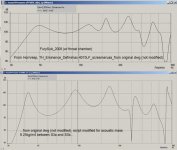
I forgot to mark the chart for the original cab as to if I used the coil or not. I prefer them without coils so it's probably without.
I'm playing tonight but I'll try to dig out all the charts and find a scanner someplace over the next couple of days.
I have to figure out when I can sneak into the club to see what a stack of 3 tests like. All 6 are now installed.
The original test cab was a 3015.
I am using both 3015LF and 4015 at the moment. The 4015 seems a little lighter on the low end but it sounds a little better to me than the 3015LF. The 3015 provides more low end.
I forgot to mark the chart for the original cab as to if I used the coil or not. I prefer them without coils so it's probably without.
I'm playing tonight but I'll try to dig out all the charts and find a scanner someplace over the next couple of days.
I have to figure out when I can sneak into the club to see what a stack of 3 tests like. All 6 are now installed.
GM said:
It wouldn't be my first choice. FWIW, this one's smaller, doesn't need an inductor, has a wider usable BW without the need of a resonator, handles more power with a much better impulse response and should smooth right out with proper lining. The possible downside is that care must be taken in preserving its flare or its HF response could be severely compromised.
Anyway, gives you another design to fiddle with.......
GM
Hi GM
")
I just noticed that the CR in this is 6.69..... I take it you think it will be ok? The AV12 has a aluminium cone which I assume would be pretty strong.
Ta
Re: FurySub_2009: model v. measurement
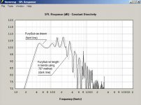
Grey line = 4015 driver
Black line = ciare 15.00sw
The ciare is easier and cheaper to get hold of in the UK, and the specs are similar to the 4015, so I was hoping to try out the ciare in screamers furybox.
Now I know the model is different to the real thing, but I was thinking if the driver specs are close enough it should still perform well?
Hi, I also tried to do this in hornresp based on the values in your script as I don't really know what I'm doing with akabak:tb46 said:I have been trying to find a way to come up with a model that reflects screamerusa's measurements, but I have not been successful
An externally hosted image should be here but it was not working when we last tested it.
Grey line = 4015 driver
Black line = ciare 15.00sw
The ciare is easier and cheaper to get hold of in the UK, and the specs are similar to the 4015, so I was hoping to try out the ciare in screamers furybox.
Now I know the model is different to the real thing, but I was thinking if the driver specs are close enough it should still perform well?
fb said:
I just noticed that the CR in this is 6.69..... I take it you think it will be ok? The AV12 has a aluminium cone which I assume would be pretty strong.
Don't have a clue. I mean I've experimented with very high CRs, but not with high Xmax drivers at high power nor have any hands on experience with THs yet other than auditioning a pair of DSL DTS-20s, but the acoustical impedance once damped should be fairly high, so I'm thinking there's going to be some damping on the backside of the driver. Only one way to know for sure.
GM
Post #570
Hi screamerusa,
It would also be important to note where the measurements where taken. If they where taken indoors room effects will definitely come into play. It's just not easy to get good measurements at the wavelength involved. That's why Tom Danley insists on the 10m measurement done in a free field.
Either way, it looks like you have come up with a fine tapped horn. It would just be nice to come to a better understanding of the differences between your measurements and the models.
Regards,
Post #573
Hi Don,
I wouldn't go as far as calling my work bogus, but then I'm probably prejudiced.
It might help if you would remodel using Hornresp with the extended section length, and then compare the two. If you search the AkAbak main manual for 'bend' it shows how they handle this.
Regards,
Hi Don,
I wouldn't go as far as calling my work bogus, but then I'm probably prejudiced.
It might help if you would remodel using Hornresp with the extended section length, and then compare the two. If you search the AkAbak main manual for 'bend' it shows how they handle this.
Regards,
Don Snyder said:Hi tb46,
I calculated Scott's horn length, and found it to be 9 inches longer than your numbers useing the .707 radii in the bends. Using the
50% line thru the bends is bogus.
If we are mounting a horn in a corner, shouldn't we include a sphere which is bounded by the dimension of the horn mounth?
Here's a pic of what I'm talking about:
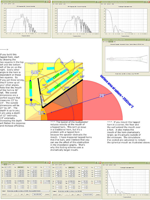
To me, this seems more accurate than aribitrarily clicking on the button in horn response for "corner loading." Because that button simply increases the efficiency, when in the real world the biggest change is that corner loading virtually lengthens the pathlength, and enlarges the mouth.
Re: Post #570
I didn't say YOU were bogus, only that the method you used was not valid (bogus). If you don't agree, show me MY error.
Bateman - In the Hornresp help files they show a graphic that defines L12, s3, etc. I take that to mean McBean wants me to
input the length to the physical edge. I assume (I know that's a dangerous word) that McBean is taking care of the "bubble."
tb46 said:It would just be nice to come to a better understanding of the differences between your measurements and the models.
I didn't say YOU were bogus, only that the method you used was not valid (bogus). If you don't agree, show me MY error.
Bateman - In the Hornresp help files they show a graphic that defines L12, s3, etc. I take that to mean McBean wants me to
input the length to the physical edge. I assume (I know that's a dangerous word) that McBean is taking care of the "bubble."
Re: Re: Post #570
Well that's why I've been ranting for a year that people shouldn't be using the "corner" loading option in horn response. As I understand it, the huge gains in efficiency will only be found if there's a smooth transition from the mouth of the horn to the corner.
In other words, to get the full benefits of corner loading, you'll need a horn with a full-size mouth.
And nobody is building horns with a full size mouth, except for this lunatic:
If I understand horn response correctly, the proper way to model a horn with a mouth that is too small is to model it in 2pi, and include a sphere that bounds the mouth.
2pi takes care of the floor, and the sphere defines the corner.
Does that make sense?
The measurements of arrayed tapped horns seem to confirm my hypothesis, as they demonstrate that the F3 does not change much when arrayed. (Because the mouth is so small.)
I posted measurements here:
http://www.diyaudio.com/forums/showthread.php?postid=1827936#post1827936
Don Snyder said:
I didn't say YOU were bogus, only that the method you used was not valid (bogus). If you don't agree, show me MY error.
Bateman - In the Hornresp help files they show a graphic that defines L12, s3, etc. I take that to mean McBean wants me to
input the length to the physical edge. I assume (I know that's a dangerous word) that McBean is taking care of the "bubble."
Well that's why I've been ranting for a year that people shouldn't be using the "corner" loading option in horn response. As I understand it, the huge gains in efficiency will only be found if there's a smooth transition from the mouth of the horn to the corner.
In other words, to get the full benefits of corner loading, you'll need a horn with a full-size mouth.
And nobody is building horns with a full size mouth, except for this lunatic:
If I understand horn response correctly, the proper way to model a horn with a mouth that is too small is to model it in 2pi, and include a sphere that bounds the mouth.
2pi takes care of the floor, and the sphere defines the corner.
Does that make sense?
The measurements of arrayed tapped horns seem to confirm my hypothesis, as they demonstrate that the F3 does not change much when arrayed. (Because the mouth is so small.)
I posted measurements here:
http://www.diyaudio.com/forums/showthread.php?postid=1827936#post1827936
- Home
- Loudspeakers
- Subwoofers
- Live sound specific Tapped Horn thread...