I can only take a few guesses.
1) The I believe the taper in s1/s2 is affecting compression in the throat.
2) Cancellations?
3) While a solid brace cuts the back of the horn in two, it's either the loss of volume, or the way the back of the speaker in the mouth reacts with the horn. I am pretty sure it's only my cab that has this problem as the Danley seems to have a solid one.. ?????????
There seems to be a bunch of interactions and reactions.
Side note. Last night we beat up on the system a bit, clipping the sub amps a wee bit. Much to my surprise the 3015's magnets stayed ice cold. They were getting pretty warm testing with sine waves so I was concerned. Hmmm. Wonder how much music power these things can really take.
GM said:
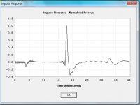
It wouldn't be my first choice. FWIW, this one's smaller, doesn't need an inductor, has a wider usable BW without the need of a resonator, handles more power with a much better impulse response and should smooth right out with proper lining. The possible downside is that care must be taken in preserving its flare or its HF response could be severely compromised.
Anyway, gives you another design to fiddle with.......
GM
GM! Thankyou again for your assistance
")
I was initially sceptical looking at the spl response graph of this design, but then I looked at the impulse response - wow! And looking closer at the SPL graph I can imagine how it might look if smoothed out with the proper lining.
When you say "preserving its flare", I take it you mean the exponential expansion? I've done some reading in these threads, mainly about approximating exponential with smaller segments.
Is y = e^x the form of the equation to calculate the area at a given distance along the path?
Do you happen to have any folding tips for this design?

Attachments
jbell said:2. Why does removing the one reflector add +3db at 100hz? hornresp doesn't have any way to model with or without it.
3. Why does a solid rear brace diminish output down low (40-50hz, I'm guessing)
screamersusa said:I can only take a few guesses.
2) Cancellations?
A 1/4wl of 100hz is 29" and your front-back dimension is 29".
Should I assume any place you have parallel walls, you can set up a resonance, and it could either be a constructive or destructive resonance and in this case it was a positive?
I think I can make that argument work, as that is the only parallel wall section in your horn with no reflectors.
However the low end and solid rear brace thing bugs me. Not dividing that horizontal dimension in two with an 'open brace' doesn't line up with a 1/4 wl of any low end frequency.
As to the issue of the front angled panels from S1-S2... and then the 12 degree reflectors -- my only guess is that the benefit here, is that no resonance of any kind can be set up close to the driver, either constructive or more importantly -- destructive.
fb said:
GM! Thankyou again for your assistance
When you say "preserving its flare", I take it you mean the exponential expansion?
Is y = e^x the form of the equation to calculate the area at a given distance along the path?
Do you happen to have any folding tips for this design?
You're welcome!
Correctomundo!
Right again!
Nothing that Tom Danley hasn't posted AFAIK (see below).
GM
==============
"Hi John, all
I would certainly second Marshal's horn paper, I have made dozens and dozens
of horns based on his math (for the driver / horn
relationship) over the last 12 years or so and his alignments
(relationships) work well, even into the HF range.
Bottom line I suppose is that the "important" part is that when you build a
real horn that it measures like the computer prediction
and since most horns I have built were not "full ideal size", having
Marshal's math as a starting point, followed by modeling of the
real thing has proven to be most powerful.
For example, when the horn mouth is smaller than ideal, it may turn out that
some other profile (other than the t = X as defined
by the computer) may provide better results. Similarly, as in the LAB
project, for cases when fewer than "ideal" numbers are
used, a somewhat different driver gave better results. With that project I
started with the "ideal" driver and then on the real horn
model used that driver as a starting point, looking at a set of 2, 4 and 6
boxes and diddling the parameters to get the best
results.
As for curves vs reflectors, it would depend entirely on the acoustic
dimensions.
As a rule of thumb, when an obstacle is under about 1/4 wl in size, sound
goes around it, no problem, the object is acoustically
invisible..
If an object is say 10 wl across, it begins to make a pretty good reflector.
In a folded horn, the bends have a direct bearing on the results higher up.
When the difference in the acoustic path length between the inside and
outside radius of the bend reaches 1/2 wl, there will be a
deep cancellation notch in the response.
This is why most all the folded bass horns I design have minimum angle bends
and those bends tend to be wide rather than deep
(to push the cancellation F's as high as possible).
For a real woofer horn though, this corner issue is a non issue.
Once we had a customer who distributed our servodrive horns in Italy.
He wanted to make his own boxes to save shipping and we said ok send us one
to look at / measure first.
He was very meticulous, had all the corners glassed in, all of the inside
was smooth and aerodynamic like an airplane part.
It really did look cool and obviously he spent a lot of time making it
perfect.
Our cabinet shop had made up a sample horn with no curves (using flat
reflectors) and another with nothing at all in any corners
except the final bend.
I measured each box with the same driver module, in the same location, with
the same mic and TEF machine.
I measured at rated power and 1/10 to see if there were differences.
The TEF machine is repeatable to a tiny fraction of a dB so the most
informative way to look at the plots was to overlay them.
The highest SPL's were from the prototype without corners, second was the
normal production model and last (about 1.5 dB
down) was the aerodynamic one.
Distortion was essentially identical for all units.
The results were sort of a surprise however on examination, it was clear
that even thought the BT-7 could produce a large
acoustic power (about 200 acoustic Watts each, in a group of 4), the air
motion in the throat and passageways was not a
sufficiently high speed to benefit from the aerodynamic treatment.
Also, that filling in the corners reduces the actual volume of air in the
horn making it "smaller" than the unfilled unit.
Granted, this box is never used above 120 HZ and usually under 80 Hz so hf
performance is not normally a concern.
One can improve some aspects of real hf performance in a folded horn of
large dimensions by using a reflector style corner.
Reflectors are common in microwave frequencies in antennas because wave
theory also applies.
With sound in a folded horn, one finds that no matter how it is done, there
is a region between where there is the 1/2 wl path
length cancellation and where the reflector really works (and remember the
acoustic path for a reflector and mass flow are also
different) that is undesirable (chaotic) so where you see reflectors used in
antenna's, they are limited to the range where they
ARE reflectors, just like with sound, the in between range is undesirable.
If one was designing a folded horn for use higher up in frequency, a second
thing to be aware of is the mode translation which
means that when the parallel walls are acoustically 1, 3, 5 etc. 1/2
wavelengths and large enough in area, there is a deep notch in
the response. This is because there is a standing wave between the two walls
which the desired acoustic output drives.
Driving the resonance also taps out the desired acoustic signal's power and
so at the mouth is a notch.
This is the source of the notch on the lab sub who's internal width is 21
inches, 1/2 wl @ 21 inches ~ 1/2 wl @ 323 Hz.
As also mentioned, the front volume (trapped between the radiator and
throat) can be sized to extend the hf response.
This uses the air volume compliance acting against the air mass in the
throat to make a low pass filter like the vent is on a vented
box.
The difference here is that the resonance defines the upper cutoff on the
horn and lower on a vented box.
This "filter" if it can be sized correctly, has an additional advantage.
The Unity, LAB sub and BT-7 all have the front volumes sized to produce the
hf extension BUT after the high cutoff the roll off
is 1 order steeper than before.
This means that the harmonic distortion that is inevitable with any driver
is attenuated before being radiated (as those harmonics
are above the cutoff).
In the Unity, the driver placement on the horn walls also adds an additional
low pass filter which further attenuates out of band
signals from being radiated. The horn loading combined with this effect are
in the Unity's which typically measure about 1/10 or
less the midband THD of anything I have measured.
On the oother hand, often it is not practical to use this trick, like hf
compression drivers where this air volume is smaller than can
be achieved as it is.
Some one also asked about compression ratio and what effect than has, I
would suggest they dig through the design part of the
LAB sub as I had written about that (from my perspective) there.
In short, compression ratio is a "transformer" and one is adjusting the
turns ratio.
Why that effects BW and efficiency is in the LAB stuff and too much to write
now.
Well, I have speakers to work on, got to run
Tom Danley
Servodrive / Sound Physics Labs"
jbell said:
Should I assume any place you have parallel walls, you can set up a resonance.........
However the low end and solid rear brace thing bugs me.
As to the issue of the front angled panels from S1-S2...
Parallel walls are half WL resonators same as room walls or an open pipe, etc.: http://hyperphysics.phy-astr.gsu.edu/hbase/waves/opecol.html#c2
I imagine the solid brace sets up a pretty severe reflection back to the throat due to a big impedance mismatch. I mean being split up at supersonic speed with no way to flow back together has got to cause some pretty severe shock-waves.
Right, the initial expansion is the horn's HF BW, so get it out of sync with the throat's BW and it affects the response all the way through its mids until the horn has become acoustically tiny and doubly so for a TH since both sides of the driver's output is in play, just compare a TH in 4pi space to its single driver variant.
GM
Thanks for posting that Danley bit. I'll be reading that another 40 times (seriously).
After all the discussion about reflectors not having any usefull effect, at the beginning of this thread: I played with them by ear and agree that they may not. It seems however to my ear, that when using sine waves I can hear many of the worst phase errors and nulls at higher frequencies. The 12 degree (roughly)reflectors are used to break up the 90 degree corners. While one might think a 45 degree would be better, my ear tells me that a 45 has little or no effect or worse makes more phase problems.
The steep angle made sense to me as to help redirect and diffract without direct cancellations. Think of a pool table where you try to use a "bounce" off the wall to get around another ball Without the cue ball and target ball colliding before the pocket.
If you draw 45 degree angles in the box you will see all the nasty "collision points" including a bounce right back down to the driver. If you omit the reflectors you get multiple notches. Perhaps someone can make more sense of this. It's a work around for a simple DIY box vs a very complex box nobody will be able to build without getting very frustrated.
(seriously).After all the discussion about reflectors not having any usefull effect, at the beginning of this thread: I played with them by ear and agree that they may not. It seems however to my ear, that when using sine waves I can hear many of the worst phase errors and nulls at higher frequencies. The 12 degree (roughly)reflectors are used to break up the 90 degree corners. While one might think a 45 degree would be better, my ear tells me that a 45 has little or no effect or worse makes more phase problems.
The steep angle made sense to me as to help redirect and diffract without direct cancellations. Think of a pool table where you try to use a "bounce" off the wall to get around another ball Without the cue ball and target ball colliding before the pocket.
If you draw 45 degree angles in the box you will see all the nasty "collision points" including a bounce right back down to the driver. If you omit the reflectors you get multiple notches. Perhaps someone can make more sense of this. It's a work around for a simple DIY box vs a very complex box nobody will be able to build without getting very frustrated.
screamersusa said:Thanks for posting that Danley bit.
The steep angle made sense to me as to help redirect and diffract without direct cancellations.
If you draw 45 degree angles in the box you will see all the nasty "collision points" including a bounce right back down to the driver.
You're welcome! He wrote a bunch more which should be in the PSW Labhorn forum archives.
Right, the higher the frequency, the acoustically wider the bend arc must be as proven by the Nautilus shell.
Note that due to boundary losses the reflection angle will be somewhat less than the angle of incidence, so without knowing the material's reflection impedance there's no way to accurately plot reflections, though if you make the reflectors out of steel the phase angle losses are probably low enough to be 'close enough' to angle in = angle out for the frequencies of interest here.
GM
TB46
I am using a 45 degree for that one although I tend to err on the side of caution and throw it off a couple of degrees so that the face of the board is slightly up. For now 45 is fine.
The two 12 degree parts: If you look carefully at the 3rd picture down on the page you can see how they were atached.
The entire board should be exposed. One edge gets a roughly 12 degree edge (the smaller 3/4 edge cuttable by most mortals with an ordinary circular saw).
The other edge sits on top of the board under it. Aside from a healthy amount of poly glue on the underside, I use the poly glue as a caulk to create a good rounded seal.
In other words the one on the baffle has to come upward, the one on the left side top has to come outwards. Very few of us are able to cut that long angle into a 21" wide board, on edge no less.
Cheers
What are you drawing this with?
If it's acad, I'm very jealous.
Hi Scott,
I hear what you say, but I sure don't understand it!
Here's a cartoon of Jim Bell's Tapped Horn. I have added the five pathways that can
cause 1/2 wavelength reflections and cancellations. If we hope to use this cabinet
for 36 to 120 Hz, and our crossover is 18dB/octave, we don't care if a hole in the
response above 240 Hz is down 18dB or 100dB, 'cause you'll never hear it over the
midbass. Only the spikes are problems, but we can EQ them out
The 146 and 196 Hz reflections could use some help, but I can't see what harm the
others are going to do.
Hi GM,
You know much more about horns than I'll ever know, but your reference to supersonic
blew me away. The wave is going at (not above) the speed of sound, and there ain't
no shockwave.
Attachments
Hi screamerusa,
Yes, I use ACAD, have been since the early 1980s. I plot the drawing, or a section thereof to the free version of PrimoPDF for attachments.
http://www.primopdf.com/
Regards,
Yes, I use ACAD, have been since the early 1980s. I plot the drawing, or a section thereof to the free version of PrimoPDF for attachments.
http://www.primopdf.com/
Regards,
That is an interesting pic and description there Don...
I would be one of the LAST ones to knock JBells box. After all, it's all his fault I attemped to build these anyway. Yeah JB, its all YOUR fault!,


One thing other than size that was an issue for me, was compression. I wanted higher compression to help protect the driver as we do beat the hell out of them.
I have found that boxes like the nexos blow without warning because there is basically no compression.
I must admit it's also VERY nice to have my 40-60hz eq flat with the th's instead of boosted with double 18's. I'll let you know how 6 sound later in the week.
I would be one of the LAST ones to knock JBells box. After all, it's all his fault I attemped to build these anyway. Yeah JB, its all YOUR fault!,
One thing other than size that was an issue for me, was compression. I wanted higher compression to help protect the driver as we do beat the hell out of them.
I have found that boxes like the nexos blow without warning because there is basically no compression.
I must admit it's also VERY nice to have my 40-60hz eq flat with the th's instead of boosted with double 18's. I'll let you know how 6 sound later in the week.
Thanks scott.... I'm glad to know someone that has gone through roughly the same thing as I. We both had a virtual gun pointed at us, no money for big $$$ cabinets, a deadline with no option other than "it will work", and our name on the line.
Necessity is the mother of invention... and sometimes, it is a mother....
I like your cabinet a lot, it's miles ahead of mine in terms of general usefulness and tone. And yea, some compression in these cabinets is a good thing.
The best part, is that they are not -13db@40hz, and don't have to have a corner to work.... flat to 40 without eq is a beautiful thing.
I know I've said it before, you've earned your success -- thanks for sharing.
Don Snyder said:
Hi GM,
You know much more about horns than I'll ever know, but your reference to supersonic
blew me away. The wave is going at (not above) the speed of sound, and there ain't
no shockwave.
Greets!
Dunno, the way it was explained to me ages ago is that since there's temp/pressure changes in the horn, ergo S0S changes, you get more severe impedance mismatches than in simple eigenmodes (standing waves) when grossly upsetting horn action, so used 'shock-wave' more as a descriptive term than meaning the results of a single high pressure change such as a car backfiring. Then again, having seen what a PA horn can do to a driver, I wonder if true shock-waves do occur in them.
GM
Forget acoustics for just a minute and humor my uneducated layman's point here:
You are dealing with manipulating air pressures in an expanding duct. Pressure decreases as the duct expands, conversely the pressure increases as the duct contracts. In a normal horn you are only concerned about the expansion, in a tapped you have to consider BOTH!. Turbulence and air density will affect sound waves, therefore it is my theory that unwanted turbulence in the cabinet as well as pressure differences can drastically effect the cabinets performance. Remember in a tapped we have sound waves going in two different directions, in different phases, causing cancellations and intermodulations.
Not only are we trying to naturally amplify sound with a duct, or impedence match the speaker to air, but we are also doing the exact opposite of what an air conditioning duct does. An ac duct distributes the air pressures evenly around a space, we are trying to concentrate air pressure from a single point.
Tricky box but rewarding results.
If you mount a 12 inch driver in a 3 foot horn, take it to the beach:
In the calm air everything is fine, as the wind picks up the sound seems to "drift" in the same direction the wind is blowing. Now if the wind starts hitting the cabinet head on, the spl starts to go down very noticably as the pressure in the horn rises. This is very noticable in hf horns. Since the horn is getting blasted in reverse, the pressure at the speaker cone becomes very high compared to the wind pressure outside the box. So you turn it up to compensate and burn up the driver.
Occasionally if the speaker is older, the cone actually breaks apart into the rear chamber. Going back to the TH, the end of the speaker firing into the mouth is sending a presure wave back up the horn to the front of the cone. I think by omitting that one reflector, not only do we have a "bounce" (I was trying for 90-100hz WL), but we also have a way to break up some of that reverse pressure wave. This may be the real reason why there is a 3 db increase at 100 without the reflector. Perhaps a decrease in reverse cone pressure (damping) is helping this thing work.
My head hurtz when I think sometimez...
I do expect to be corrected on this one....
MikeHunt79 said:This is interesting stuff guys, and after seeing that pic Don just posted I was wondering if this would mean that folded TH's would have less cancellations over non-folded TH's below 100Hz or so?
More folds equal shorter straight paths, so sure, the cancellations are at higher frequencies. But wait ... now there are more bends,
and Tom has told us that bends have their own cancellation problems. Tom said it's best to make major bends where the horn
is small (the throat end).
Lions and Tigers and Bears, oh my!
Assuming horns adhere to the physics of room 'slap echo', then the angles need to be >12 deg WRT the expansion for them to be ~completely effective.
Also, is structural foam in relatively thin thicknesses even remotely rigid/massive enough to handle the reflections in a mid-bass/woofer app?
GM
Also, is structural foam in relatively thin thicknesses even remotely rigid/massive enough to handle the reflections in a mid-bass/woofer app?
GM
Typical structural foam maximum loads are well above 10 lbs per square inch, while loads in tapped horns due to sound are
well below 10 lbs per square foot. John (below) used cheesy styrofoam.
From John Sheerin's website: http://ldsg.snippets.org/HORNS/sub.html
"Something else that had been hovering in the back of my mind was that I would have to move this beast after only a year's
time; I'll be graduating and moving somewhere else. This is what prompted me to think of using foam for a substantial part of the
box's construction. My thought was that this would save weight, and thus my back. This construction method would also have the
advantage of letting me make smooth curves for the horn flair using a hotwire cutter. Whether or not smooth curves in a bass
horn provide any audible benefit is debatable, but I did not want any frequencies much above 100hz, so there was nothing wrong
with this approach (reflectors should be better for reducing high frequency attenuation through the bends). In addition, having a
sharper acoustical cutoff above 100hz should help reduce harmonic distortion by naturally attenuating the upper harmonic
frequencies."
- Home
- Loudspeakers
- Subwoofers
- Live sound specific Tapped Horn thread...