Your Power Zero Volts plane is under all the smoothing capacitors. That will keep the HF components of any fast changing currents in very low loop areas and minimise interference emanating out into the Buffer.
The Buffer has a Signal Ground plane under all the components. That too allows all the HF signals to maintain low loop areas.
I see only one cut in this plane and there are no components, nor traces, passing across the cut. That is good.
Now, since I know very little about ground and power planes, I have to ask a question:
Q, do we need to introduce a cut, or two, between the power zero volts plane and the Signal Plane, to force current flowing from PSU to Buffer to follow a preferred route?
Or do we get a good route by leaving the plane uncut?
Hi Andrew,
I asked this question to myself too. My intention was to create a sort of "star" ground under the op-amp. I initially wanted to introduce more cuts into the ground plane separating signal in/out returns and the power returns but this would shrink the connection between power ground and signal ground under the op-amp. I guess that the cut I made would force the return currents to pass under the IC and do not wander around especially at low frequencies. May be someone more skilled in the art can help to make it clear.
Regards,
Oleg
Hi Oleg,
I would extend the bottom layer ground plane to the whole surface.
Diode bridge traces will radiate much less if on a ground plane.
I would remove the upper layer ground plane, particularly in the left half of the board, it's pretty useless, IMHO.
Also I will make some cutouts on the groundplane between smoothing caps.
I will post later some examples from commercial gear.
In the right area I will, instead, create a signal ground plane and join it to the main ground via a resistor or a ferrite bead.
Also, since you're not using electrolythics on regs output you shoud keep power lanes MUCH shorter, maybe you could move the opamp between regulators and use regular power traces instead of planes.
Hi Dario,
Thanks a lot for the tips.
I will extend the ground plane under the rectifier diodes as you suggest.
As for the top ground plane I think it should be there because of SMD parts on top which connect to it. I would not like using via for each SMD cap. The through hole filter caps effectively connect to both sides of course. I would say it should not harm having it.
The cut outs in the ground plane are not so clear to me. I'll wait for your examples.
Connecting signal and power grounds using a resistor does not sounds right to me. Ferrite bead - may be, but both increase an impedance of the current return path which as I read here and there is a bad idea. Could you please give an argument why it is good and what benefit should I have from doing it? In principle in my naive thinking ferrite beads belong to power lines, IMHO.
The last argument is a bit confusing. The board size is relatively small (3x8 cm) and the distance from the 10uF ceramic cap (at the output of each reg) to the op-amp is around 1 cm and there is another pair of 0u47 caps at the power pins of the op-amp. Is it still too far?
Also using power traces instead of power pours/planes would increase the power lines inductance and reduce the extra capacitance. The extra capacitance between power and ground planes is typically attributed as positive while lower inductance makes the 10uF caps "closer" to the op-amp, IMHO.
But I'll think on moving the op-amp closer/between the regs anyway. It should in principle fit without making the board wider and it can also make the board shorter which is a plus.
Regards,
Oleg
Last edited:
Thanks a lot for the tips.
You're welcome.
I will extend the ground plane under the rectifier diodes as you suggest.
Fine, use the whole surface of the board.
As for the top ground plane I think it should be there because of SMD parts on top which connect to it. I would not like using via for each SMD cap. The through hole filter caps effectively connect to both sides of course. I would say it should not harm having it.
I'm not suggestig to necessarily remove thee whole upper ground plane but the part on the left area of the PCB.
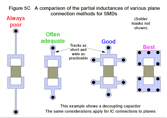
(From: PCB DESIGN TECHNIQUES FOR LOWEST-COST EMC COMPLIANCE)
Other useful documents to read:
http://www.analog.com/library/analogDialogue/archives/39-09/layout.pdf
http://www.analog.com/media/en/tech...14948960492698455131755584673020828AN_345.pdf
http://www.elmac.co.uk/pdfs/Lord_of_the_board.pdf
http://www.ti.com/sc/docs/apps/msp/journal/aug2000/aug_09.pdf
The cut outs in the ground plane are not so clear to me. I'll wait for your examples.
These examples are not a ground plane but they illustrate what I'm referring to.
Note that you can't implement them without the removal of the upper ground plane in the smoothing caps area.
Connecting signal and power grounds using a resistor does not sounds right to me. Ferrite bead - may be, but both increase an impedance of the current return path which as I read here and there is a bad idea. Could you please give an argument why it is good and what benefit should I have from doing it? In principle in my naive thinking ferrite beads belong to power lines, IMHO.
In an application like a power amplifier having power and signl ground it's a good practice but maybe here it's not needed.
Ferrite beads behve like inductor and they can be effective ddevices for decoupling.
The last argument is a bit confusing. The board size is relatively small (3x8 cm) and the distance from the 10uF ceramic cap (at the output of each reg) to the op-amp is around 1 cm and there is another pair of 0u47 caps at the power pins of the op-amp. Is it still too far?
I've missed the 10uF ceramic... BTW I would use Tantalum or even better Niobium caps in that position.
Paralleling two low ESR ceramics is not a good thing...IMHO
Also using power traces instead of power pours/planes would increase the power lines inductance and reduce the extra capacitance. The extra capacitance between power and ground planes is typically attributed as positive while lower inductance makes the 10uF caps "closer" to the op-amp, IMHO.
But a trace, eventually a WIDE one, on a groundplane will also have controlled impedace, which IMHO is a good thing.
Also the impedance is kept low by the decoupling caps.
But I'll think on moving the op-amp closer/between the regs anyway. It should in principle fit without making the board wider and it can also make the board shorter which is a plus.

Attachments


Thanks a lot for the examples!
As I understand from the examples the intention of the cuts in the ground plane is to force the return currents to go through the "ground" pins of the smoothing capacitor. This in principle can help at low frequencies when the return current may deviate from following the forward current. But if the source of the forward current in the capacitor itself the return current would arrive at the correct "ground" pin of it anyways. May be it is only needed if multiple bulk capacitances spread across the board?
I am still not fully grasping the need for the cuts but I'll research further. If I better understand their purpose I may consider making them. Actually the cuts can be implemented on both, top and bottom, ground planes if needed.
I'll read more on paralleling of several low ESR capacitors and the effect it may have.
Thanks a lot for giving me some information to think about🙂 It makes it fun!
Regards,
Oleg
I modified the PCB. Thanks to Dario's suggestion it is 1 cm shorter now.
The capacitors C11 and C12 can be tantalums (1206 size).
I guess the design is approaching its final version for now.
Regards,
Oleg
The capacitors C11 and C12 can be tantalums (1206 size).
I guess the design is approaching its final version for now.
Regards,
Oleg
Attachments


Slow progress...
Hi,
I have finally found the time to assemble some of the boards.
Burned one PSU board with regs while learning how to use solder
paste and hot air re-flow station. Thermal pads are a bit tricky
to solder. Let's see if the one which seems OK is working.
The K170BL's are matched pretty well. Got them from e-bay as
a matched octet with Idss ~ 7.41mA (+-1/%), retested by myself
and one appeared to be a true outlier. Still have enough good pairs
for 2 buffers.
Next comes the PSU test and LME49990 boards...
Regards,
Oleg
Attachments

Last edited:
Progress
My formerly passive preamp is slowly going active...
The regs are working. Can't say if they are as "silent" as they should be. The voltages are set to +10V - 0 - (-10)V and I get +10.00V - 0 - (-10.04)V on the output. The difference is probably due to the slightly different Vref for the neg and pos regulators and I used the same voltage setting resistors for both. I guess it should not be a problem. Next is to stuff the K170BL's into the sockets and listen. The left side of the preamp is currently in use in my system as the passive volume control. Will see how the active side using B1's would compare... Then LME's... then final decision and then the front panel design🙂
Regards,
Oleg
Attachments


Hi Oleg,
Just asking as the term drives me nuts.
-Chris 🙂
Just what exactly is a "passive preamp". A preamp is an amplifier before something. That requires power to be added to the signal to make it higher in amplitude, or higher in current. Without a power source and amplification stage, there cannot be a "preamp".My formerly passive preamp is slowly going active...
Just asking as the term drives me nuts.
-Chris 🙂
Hi Oleg,
Just what exactly is a "passive preamp". A preamp is an amplifier before something. That requires power to be added to the signal to make it higher in amplitude, or higher in current. Without a power source and amplification stage, there cannot be a "preamp".
Just asking as the term drives me nuts.
-Chris 🙂
That's why I call the Lightspeed passive Attenuator, even though it has an active component the led, the L&R signal only travels through ldr passive component.
As preamp stands for pre-amplifiaction, which means it amplifies, has gain and is active.
Even a passive with a unity gain buffer, should not be called a preamplifier, it's an active buffered volume control.
Cheers George
Last edited:
Hi George,
I have no problem with "Lightspeed Passive Attenuator", except that it doesn't drive cable or input stages very well. But, calling an attenuator a "passive preamp" seems to be trying to give the attenuator qualities it doesn't have. Just call it an attenuator, because that is what it is.
How about a gain of approx +6 dB? That might strike a nice balance between loss only and too much gain.
-Chris
I have no problem with "Lightspeed Passive Attenuator", except that it doesn't drive cable or input stages very well. But, calling an attenuator a "passive preamp" seems to be trying to give the attenuator qualities it doesn't have. Just call it an attenuator, because that is what it is.
Now this is much preferred. This can drive cable and input stages. "Buffered VC" is descriptive enough, or "Buffered Attenuator".a passive with a unity gain buffer, should not be called a preamplifier, it's an active buffered volume control.
How about a gain of approx +6 dB? That might strike a nice balance between loss only and too much gain.
-Chris
Hi George,
except that it doesn't drive cable or input stages very well.
-Chris
This is a big furphy, show me the math. https://www.google.com.au/#q=furphy
So long as the source output impedance is say <500ohms which most are, and has an output voltage equal to or more than poweramps input sensitivity, which most are. There are no problems.
The Lightspeed mimics a 10kohm passive pot, it's output impedance is at worst case 2.5kohms this drives any poweramp 33kohm or higher, which most are.
The interconnects at 1-2mts at 100pf per foot or less capacitance which most good quality ones are, has no effect on the high frequency. because at 2mts 100pf per ft you'll have approx. 600pf this combined with the worst case output impedance of 2.5kohm gives a HF roll off at -3db @ 106khz!!!
And if you don't believe me, maybe Nelson Pass can help think again.
" Nelson Pass,
We’ve got lots of gain in our electronics. More gain than some of us need or want. At least 10 db more.
Think of it this way: If you are running your volume control down around 9 o’clock, you are actually throwing away signal level so that a subsequent gain stage can make it back up.
Routinely DIYers opt to make themselves a “passive preamp” - just an input selector and a volume control.
What could be better? Hardly any noise or distortion added by these simple passive parts. No feedback, no worrying about what type of capacitors – just musical perfection.
And yet there are guys out there who don’t care for the result. “It sucks the life out of the music”, is a commonly heard refrain (really - I’m being serious here!). Maybe they are reacting psychologically to the need to turn the volume control up compared to an active preamp."
Cheers George
Hi George,
It's the cable capacitance that can be the big problem. Possible hum pickup is another (the output stage forms a voltage divider). These things can depend on the wire used, so there is a lot of latitude here.
With a buffer, those issues go away.
-Chris
It's the cable capacitance that can be the big problem. Possible hum pickup is another (the output stage forms a voltage divider). These things can depend on the wire used, so there is a lot of latitude here.
With a buffer, those issues go away.
-Chris
I did the capacitance math for you -3db 106khz worst case 2mts.
No hum in fact quieter than an active stage, in fact even unshielded interconnect is fine. You need to believe NP if not me.
Cheers George
No hum in fact quieter than an active stage, in fact even unshielded interconnect is fine. You need to believe NP if not me.
Cheers George
The line out of the unbuffered attenuator could be >150pF/m and it could be ~5m long.
The next stage could have 750pF of RF attenuation at it's input.
The F-3dB = 35kHz with an Rs (output impedance of the Source) of 3k
F-1dB ~ 18kHz
Add on a Buffer with a current capability of 5mApk and output impedance (an added resistor) of 100r and F-1dB increases to ~550kHz.
far too high for effective RF attenuation in our interference riddled homes.
One adds a 1k resistor inside the Receiver to turn it's 750pF into a F-3dB=210kHz RF filter. F-1dB ~ 120kHz
The Buffered attenuator with an effective RF attenuator inside the Receiver drives short and medium length interconnects without having to be concerned with losing some audio information.
Long interconnects, exceeding 10m, would require a more current capable Buffer and maybe even need changing to balanced impedance to give adequate interference and RF tolerance.
ps.
there are many Members on this Forum that believe they can hear reduced audio information with the RF filter set to 200kHz (0.75us for RC). They prefer using 0.1us to 0.47us of RF attenuation RC to ensure they receive all of the audio information.
Last edited:
Hi Andrew,
Thanks for your comments. This is the point I was attempting to make.
Hi George,
The lower the output impedance of a buffer stage is, the less noise will survive to pollute the audio signal given an identical interfering field between various attenuator and buffer designs. These laws of physics apply equally to all attenuators or output buffers. This reality is in the physics of the situation, not in a quote from someone.
Keep in mind that I have the greatest respect for Nelson Pass. I think you may have misinterpreted something he said, or it is out of context.
-Chris
Thanks for your comments. This is the point I was attempting to make.
Hi George,
Just so you know, my experience in the real world differs greatly from your post. Unshielded interconnect is sometimes okay as long as it is twisted and the twist rate is high. Try using the Wht / Blu pair from LAN cable as an example. This is about the best case situation. I think your assumptions about capacitance are overly optimistic, but that's okay.No hum in fact quieter than an active stage, in fact even unshielded interconnect is fine.
The lower the output impedance of a buffer stage is, the less noise will survive to pollute the audio signal given an identical interfering field between various attenuator and buffer designs. These laws of physics apply equally to all attenuators or output buffers. This reality is in the physics of the situation, not in a quote from someone.
Keep in mind that I have the greatest respect for Nelson Pass. I think you may have misinterpreted something he said, or it is out of context.
-Chris
I'm not advocating the use of unshielded, I'm just say there is no hum even with it.
Yes your buffer points come into play only if the interconnects are 10mt or the poweramp has a stupid low 1-10kohm input impedance
Otherwise for 1-2mts interconnects (or as Andrew points out even more. I like my -3db at 100khz) and with sources that have low output impedance (<1k) and poweramps that have >33kohm or higher input there is no advantage in having a buffer after a 10kohm volume pot, in fact in can only be slightly detrimental/coloured, as none are perfect.
Cheers George
Last edited:
- Status
- Not open for further replies.
- Home
- Source & Line
- Analog Line Level
- Line level buffer: discrete or ICs based?