Hey common guys, take it over to the Vendor's Bazaar, this is just as bad as Chris Daly pushing his his wares all over again.
Cheers George
 Even thought I have too many projects head of this, I still come here to read about your efforts George
Hi George,
I originally mentioned the VCCS (Voltage Controlled Current Source) on this thread purely as a DIY enthusiast who required remote control for his own system and had subsequently developed a remote control to fulfil this need.
The VCCS remote control project was originally set up in response to requests from DIY Audio members on this thread to provide information about this VCCS. It quickly developed into a request for a group buy.
At this point I asked you if it was acceptable to post details of the VCCS remote control in the thread or if you would prefer me to set up a new thread for the remote control project. You gave me permission to post information about the VCCS remote control in your thread as it was a “not for profit” project and, in the spirit of the thread I was happy to publish all the technical details for DIY enthusiasts to implement their own remote control.
It still is a “not for profit” project, but if you have decided this is no longer a good idea because others are posting about their developments with a view to attracting commercial attention, that’s fine. I will refrain from posting about the VCCS on this thread in the future. If you want to have the admin crew transfer all posts referring to the VCCS project to a new thread I am OK with this.
My original offer of free use of the design in your own Lightspeed production products still stands if you wish to make use it (This should not be seen as carte blanche permission for others considering using the design commercially).
Regards
Paul
Hey common guys, take it over to the Vendor's Bazaar, this is just as bad as Chris Daly pushing his his wares all over again.
Interesting. I always came at this thread as a place to discuss LDR attenuators, the Lightspeed being the first and most simple type of them.
If it's a place for business, even if George's, the whole thread should be moved to Vendor's Bazaar. Group buys and non-profitable efforts like that of Paul are far from being a business.
Last edited:
George has never pushed his products on this thread, nor IMHO has Maximus. Uriah Dailey, the main (sole?) supplier of matched LEDs for DIY Lightspeed builders, hasn't even mentioned his own CCS-based design on it. I think it's fair to say that some others have not always been as respectful of the thread's integrity and that George makes a fair point.If it's a place for business . . . the whole thread should be moved to Vendor's Bazaar.
If it were to become just another vendor thread, that'd be a pity.
Carlos,
The remote control modules do indeed control a digital pot and this in turn controls 4 voltage controlled constant current sources that drive the LDR LEDs.
The boards and modules were priced to cover the costs of provision and no business profit was added. If I were to add a business profit margin the prices would have been somewhat higher.
Rylands and Andrew,
George may have thought that my recent post was commercially orientated, but it was just to point out that CCS operation was not new on the thread. I added the information about the modules still being available and at the same prices to avoid posts and e-mails asking for this information, which is already on the early sections of the thread.
Regards,
Paul
Interesting. I always came at this thread as a place to discuss LDR attenuators, the Lightspeed being the first and most simple type of them.
That's also my take on it, as demonstrated by past history of alternate LDR designs presented in this thread over time. I'm also posting stuff I do as a hobby only.
That's also my take on it, as demonstrated by past history of alternate LDR designs presented in this thread over time. I'm also posting stuff I do as a hobby only.
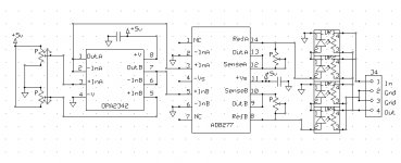
Here is a contribution to the ‘dead easy’ constant current LDR volume control discussion. I’m not trying to sell anything here. This circuit works well, and consists of only a dual ganged pot, two ICs, two multi-turn trimmer resistors, four LDRs in series/parallel, and a few bypass capacitors. I'm assuming that with a little thought, you could do a circuit for the op-amp that would take care of the "one-side goes up when the other side goes down" requirement which would allow you to do away with the dual ganged pot. In my circuit, I do it with software so haven't worked on a hardware solution.
Virtually no current flows through the volume control pot, so that is not a problem at any volume setting.
The constant current IC is internally current-limited to 15ma max per leg, and at that current through two series LEDs, it delivers an easy 25 ohm -- or better -- minimum resistance. Since you only draw max current through one side at a time, the total current through the IC is always 15ma or less, though the chip is capable of delivering 30 ma (15ma per side). You could do this circuit with only one LDR per leg, but you get a better attenuation range by using two at the same 15ma, and there is no downside other than cost.
The only downside to this circuit is that it uses SMT ICs. If anyone can find equivalent DIP ICs, I’d love to hear about them. In selecting alternatives however, beware, because you will find the devil in the details. I like these ICs because they are precision, and the CC chip uses precision laser-trimmed resistors for minimum temperature drift in operation. The math for calculating the values of the reference resistors on the output is simple and is included in this article.
Difference Amplifier Forms Heart of Precision Current Source: Analog Dialogue: Analog Devices
Wapo54001
Attachments
Last edited:
With a single pot, wouldn't the supply just be connected to the wiper and the ends be connected to the current-limiting resistors of the series and shunt attenuator's two LED circuits?
Or, given a single variable voltage within a known range from zero to vmax, a one-opamp subtraction (difference) amplifier could be used to subtract the variable voltage from a vmax reference voltage, giving the reverse-varying voltage needed for the other LED in a series/shunt attenuator.
But the second case gives very different results, with a Lightspeed II-type attenuator.
Last edited:
post4690
The link to the Analog Devices paper on the precision CCS.
Look at fig4, it is a Howland current pump. It is virtually identical to the CCS implementation in Mauro Penasa's MyRefC chipamp Power Amplifier.
The authors do not credit Howland.
The authors and AD should be strung up.
Since it is a Howland. All the advertising for AD opamps can be ignored. Just substitute any FET input opamp and add on the 4 matched resistors. 411, 071, 134, etc can all be used. You can add on the output transistor for extra current drive if you need it, but the LEDs will be happy with a maximum of 19 to 20mA.
Similarly you can add on the feedback buffer, if you think you need the extra precision.
Q1.) how do we convert the +voltage reference to an inverted version?
Q2.) How do we create a form of log law voltage reference for both the +ve and the inverted version?
Q3.) how do we trim the log law to some other compression ratio to suit how the user wants his volume control to "feel" as one turns the knob?
I don't know who Howland is, or know anything about his pump. I just found a circuit that I liked and wanted to share it. If you want to string up the authors, find a posse and have at it, but I won't be riding with you.
I like the AD integrated solution for multiple reasons:
One, it is very small -- the SMT chip is maybe half the size of a DIP with the same number of pins. When you add four external resistors to each discrete circuit -- eight per channel -- the fully integrated version becomes even more attractive.
Two, to avoid temperature instability, the resistors must be very close tolerance (better than 1%). On top of the extra space external precision resistors would take, I don't want to pay for that kind of quality.
Three, the AD device is current limited to 15ma -- perfect for running two LEDs in series to achieve 20~25 ohms resistance. I don't have to worry about limiting current.
Regarding your questions 1,2, and 3, I don't have an analog answer for you because I don't have to deal with it. Instead, I use a PIC to custom program each LDR leg any way I want it to respond. The PIC has 1023 linear steps which is really not enough to properly control the LDR across the full spectrum from 25 ohms to, say, 20K ohms; however, by using two Vrefs, I can change the PIC behavior to give not only 1023 steps across the entire current range of 15ma to .002ma, but also a separate 1023 steps from .2ma to .002ma, and that really does cover the waterfront quite well.
I think that in my own project I've been spinning my wheels trying for a degree of precision control that the LDR simply will not support due to the sloppiness of it's response to changes in current and whether the change is either up or down. I can precision-control the current, but the LDRs don't want to cooperate at that level! The LDR is what it is, and it won't get any more manageable.
Your questions are valid ones. In my opinion they apply equally to the Lightspeed and all other implementations that do not include digital management of the LDR response curve and individual device differences. However, I believe that an active feedback-based control element (op-amp) monitoring and controlling current is theoretically superior to the 10K pot driving the LDR directly. Maybe in real life it isn't. Let's try some and find out.
The link to the Analog Devices paper on the precision CCS.
Look at fig4, it is a Howland current pump. It is virtually identical to the CCS implementation in Mauro Penasa's MyRefC chipamp Power Amplifier.
The authors do not credit Howland.
The authors and AD should be strung up.
Since it is a Howland. All the advertising for AD opamps can be ignored. Just substitute any FET input opamp and add on the 4 matched resistors. 411, 071, 134, etc can all be used. You can add on the output transistor for extra current drive if you need it, but the LEDs will be happy with a maximum of 19 to 20mA.
Similarly you can add on the feedback buffer, if you think you need the extra precision.
Q1.) how do we convert the +voltage reference to an inverted version?
Q2.) How do we create a form of log law voltage reference for both the +ve and the inverted version?
Q3.) how do we trim the log law to some other compression ratio to suit how the user wants his volume control to "feel" as one turns the knob?
Yeah, string 'em up! <smile> I haven't looked at it but it sounds like an egregious transgression on their part.
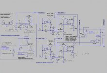
Re Q1: Are you talking about the "reversed" (not really "inverse") version, for the other LED? If you have a ramp then you just subtract it from its maximum value and you get the opposite-going ramp. But for the log-like voltages that are produced by a linear pot, you have to put the ramp and the created opposite-going ramp each into their own log-response circuit. But maybe it should be a 1/x circuit, because I'm having trouble getting the shapes to match, using log.
Re Q2: National's AN-31 (among others) has a temperature-compensated log circuit or two. I've actually got the whole thing running in LTspice, with both LED currents being derived from a single voltage source (e.g. a ramp, for testing). Using software instead of analog would probably be a lot easier, for the designer at least.
Re Q3: We could, for example, change the log circuit's resistors (I actually have three of the resistors in my log-generator labeled, in my sim, as "corner tighter", "end lower", and "unflatten"). But I have to say it's been a pain trying to tweak them "by hand", to more-or-less match a potentiometer's responses.
However, the basic problem of getting a lower output impedance and a higher input impedance remains a problem.
I haven't had enough time to play with all of this stuff. And I'm leaving for the weekend, tomorrow. So it'll have to wait, unfortunately.
Attachments
Last edited:
So, I have a question for the owners and originators of the Lightspeed thread. There has now been a good sample of the various thought processes that are proceeding in the constant-current mob.
Question in my mind is, do these posts elicit curiosity and interest, or do they elicit a grinding of teeth and a wish that it would all go somewhere else?
I personally don't want to continue where this conversation really is not welcome. On the other hand, I know that this method is where future LDR applications are headed, and maybe it is welcome here. I would appreciate some kind of overt decision by the people who rightfully own/control this thread so I would know where to go with future discussions along these lines.
Outside the Lightspeed thread, LDR posts are fragmented, and the constant-current proponents have nowhere to share and introduce concepts with a wider audience. I think the concentration of enthusiasts and experienced LDR users here is the main draw.
Shall we go away and try to start the "LDR Constant-Current Control" thread?
At least two have been started.
The first fell apart due to the originator knowing almost nothing about how currents flow.
The second is waiting patiently.
http://www.diyaudio.com/forums/anal...light-dependant-resistor-current-control.html
http://www.diyaudio.com/forums/anal...on-ccs-control-led-ldr-volume-adjustment.html
The first fell apart due to the originator knowing almost nothing about how currents flow.
The second is waiting patiently.
http://www.diyaudio.com/forums/anal...light-dependant-resistor-current-control.html
http://www.diyaudio.com/forums/anal...on-ccs-control-led-ldr-volume-adjustment.html
At least two have been started.
The first fell apart due to the originator knowing almost nothing about how currents flow.
The second is waiting patiently.
http://www.diyaudio.com/forums/anal...light-dependant-resistor-current-control.html
http://www.diyaudio.com/forums/anal...on-ccs-control-led-ldr-volume-adjustment.html
I love the lasts dozen posts or so in that first link. What a scream!
Never knew the second thread had been started. Maybe all the constant current stuff should move there; Need to find a way to advertise it though. It's good stuff, but not well known.
I don't know who Howland is, or know anything about his pump.
<snipped>
See AN-1515 at national.com .
- Home
- Source & Line
- Analog Line Level
- Lightspeed Attenuator a new passive preamp