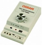
Or if you diyer's want to go a little more sexy and not have to pull the led's in and out of holes, this one has a switch for the different mA setting.
Before my own much more complex one I built, I used a regulated 9v wall wart insted of the battery to power these simple testers from Kemo and Osram.
The Osram one for memory was available from RS Components also cheap around $10
Cheers George
Before my own much more complex one I built, I used a regulated 9v wall wart insted of the battery to power these simple testers from Kemo and Osram.
The Osram one for memory was available from RS Components also cheap around $10
Cheers George
Attachments
Last edited:
And when you get there, how do you know if devices are matched or performing ? Some meaningful data, such as L/R channel balance differences, input impedance unloaded of a matched LDR set ..as supplied and built. Please. Cheers / Chris
This record is broken sckttttclickThis record is broken sckttttclickThis record is broken sckttttclickThis record is broken sckttttclickThis record is broken sckttttclickThis record is broken sckttttclickThis record is broken sckttttclickThis record is broken sckttttclick
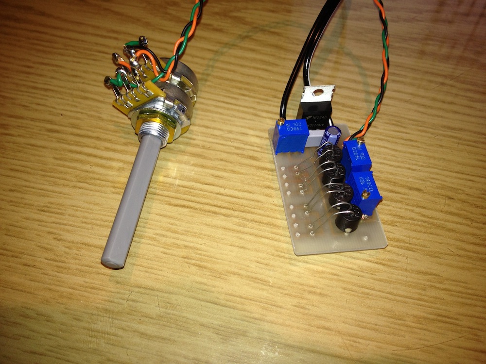
Though I would post a picture of my Lightspeed built on a custom PCB using the 'Laser toner' method. I haven't tested it with audio yet as I haven't had time to build the amp yet, but when I adjust the volume pot, the resistances of the LDR outputs change as they should and the resistances are pretty close.

Hi BFNY, yes, that is the CCS I referred to.
OK, thanks. FYI the VCCS circuit I use for matching LED/LDRs, and for control, is similar to the one shown here
Voltage Controlled Current Source - Current Servo
You put the LED above the mosfet. I use BS170 mosfets. You also need to use rail to rail op-amps.
Attachments
Have I received "points" too? I notice that my post was deleted, although Chris's was not. Did I do something wrong? I have not received any PM or email about that. What are "points" anyway?chris have received points, and a warning to stop trolling in another mans pond
moderation
Have I received "points" too? I notice that my post was deleted, although Chris's was not. Did I do something wrong? I have not received any PM or email about that. What are "points" anyway?
I confess some confusion. I started a rather extensive post in response to the constant current schematic which BFNY has just posted, but backed out because I wondered if perhaps it was getting too far into constant current and this is the Lightspeed thread, and there have been rumblings about this problem for a long time now.
It's a conundrum. The Lightspeed is a very simple yet very musical (so I'm told, anyway, I've never heard one) circuit. So the value of the LDR is proven. But future development will invariably move in the direction of constant current because of the nature of the LED side of the LDR, and because of the desire for more precision and control over how the LDR functions in the circuit. What I'm not sure about is whether this thread is for the maintenance of the Lightspeed circuit, or whether it is about LDRs and the continuing evolution of the use of LDRs in audio.
The constant current circuit that BFNY posted is the foundation for constant current control of LDRs. While there are a lot of nuances and devil-in-the-details issues that are not addressed in that circuit, that's the basic idea. Those of us who are seriously pursuing constant-current circuits are dealing with those nuances that require a lot of serious study and testing which put our projects out of the mainstream and, in my case at least, my project requires PIC programming expertise as well as audio expertise. No one seems to be working on a dead simple constant current circuit like the one BFNY posted that would be within easy reach of DIY audiophiles -- something that is easily and inexpensively reproducible, but delivering superior results. Maybe a combination of constant current circuitry and UDaily's matched LDRs would be an ideal compromise.
Someone needs to start a thread centering around a dead simple constant current circuit controlling four legs of LDRs using the principles shown in BFNY's circuit, and produce a viable circuit card with regulated power on board. And, if the Lightspeed folks wish it, we need to do it somewhere else. I would like to participate, but don't feel comfortable doing it here unless/until it is made clear that this thread is about expanding our understanding of LDRs and that constant current discussion is welcome.
JMNSHO.
VCCS control
JMNSHO,
The VCCS module described way back in this thread was designed for constant current control and provides 65 levels of current via a digital potentiometer. Operationally this is fine enough to get the volume to the required level. The range of operation can be adjusted to suit the system by changing the current setting resistors. It was originally designed as a group buy, for DIY use, driving George’s Lightspeed configuration. There is space on board for the LDRs or you can hard wire the LDRs off board. Uriah Daily can provide matched LDRs for this module. The VCCS module can provide volume and balance and it works very well. With matched LDRs the balance control may seem redundant but in practice it is useful for balancing out channel differences in the music source or those caused by less than ideal loudspeaker placement. Control is via push button either on the chassis front panel or/and via the matching remote control transmitter and receiver modules.
The PCB’s or built and tested modules are still available and the prices are still the same although the shipping cost has increased slightly since the prices were originally published.
High performance shunt regulators for the VCCS reference chain and an ultra low noise series regulator for the main regulator are also available to provide first class supply and control regulation. These regulator modules are easily fitted to the VCCS module.
Regards
Paul
Last edited:
JMNSHO, BFNY and others: smart ideas.
FWIW, my experience of the CCS on the LDR was fantastic and I would be very keen to pursue it further.
I would echo JMNSHO's sentiments that it should possibly be explored in a new thread.
For the record: JMNSHO = Just My Not-So-Humble Opinion
Signed, Wapo54001

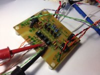
here's my proto board - as you see, this can be done in a very small space.
This uses dual rail to rail op-amps and 4 BS170s. The board is about 3" long
Mods can move this to a new thread if desired, or I can repost in a new one.
Good looking board! That looks like it could be what I was talking about earlier -- a board that lots of people could build and enjoy, and featuring tighter control of the LDR resistances.
here's my proto board - as you see, this can be done in a very small space.
This uses dual rail to rail op-amps and 4 BS170s. The board is about 3" long
Mods can move this to a new thread if desired, or I can repost in a new one.
BFNY, I'm glad a saw your board. I just realized that I'd added a lot of complexity to my design to solve a problem, and then solved the problem with a simple change to the circuit but then never went back to get rid of the unnecessary complexity I'd added! I need to test to verify, but I think my design just got a whole lot simpler thanks to seeing your board!
The PCB’s or built and tested modules are still available and the prices are still the same although the shipping cost has increased slightly since the prices were originally published.
Paul,
Where can I get some more info on this version?
Schematics, theory, pcbs, etc.?
Carlos
Hello Carlos,
All the technical information is available in the Lightspeed thread.
The VCCS and remote control module photos are shown on post 1874 page 188.
The circuit schematics are shown on post 2728 page 274.
The module prices are shown on post 1804 page 181. These prices are still the same except that, after losing a few shipments, I now ship only with an insured service and the prices for shipment are higher. I can quote for specific destinations.
Regards
Paul
- Home
- Source & Line
- Analog Line Level
- Lightspeed Attenuator a new passive preamp