No, I want you to surprise me by showing/explaining how changes in the input impedance have an effect on sound that we hear.You want me to design the inputs to that criteria
AndrewT, You have to do the changes and listen yourself. Sorry, even cutting your ears off and mailing them to me won't work.
One thing I have learned is that most engineers are restricted to the later education text books. I once asked a MS in control systems why he used a constant to represent a sensor in his thesis, his answer was "that's what they do in the textbooks". Bad answer!
One thing I have learned is that most engineers are restricted to the later education text books. I once asked a MS in control systems why he used a constant to represent a sensor in his thesis, his answer was "that's what they do in the textbooks". Bad answer!
Last edited:
This observation is relevant in what sense?soongsc said:One thing I have learned is that most engineers are restricted to the later education text books.
I said "you would be surprise..." not I would surprise you. Why would I want to surprise you? If you play around with it, I am sure you can find out the surprise.Can I conclude you have no surprise to offer based on what you claimed earlier?
Last edited:
Sorry, the whole discussion got side tracked when it entered impedance discussions using the Lightspeed. The impedance characteristics of the interface between equipment needs more attention than lots of people may think.This observation is relevant in what sense?
it's actually 680pF
That combined with the 150pF of the cable and the 47pF at the RCA comes to a total capacitance of ~880pF.
The RF filter is worst case 2k5+1k & 880pF giving F-1db @ >= 52kHz.
But I actually have a pair of cascaded passive filters neither of which have zero source impedance nor do either have infinite load impedance.
My brain and my calculator need help in deciphering that combination.
But this is all worst case, to help Soong prove his point.
I would never accept a vol pot as having adequate drive capability for any cable + amplifier arrangement.
It could easily be worse.
Someone could have decided to use a low-value resistor, to keep the noise level lower, so say a 100 Ohms right after the amp's RCA input jack and then, to make it not unreasonably bad, say 2200 pF to ground, for a 723 kHz low pass. The crazy-high 2.5k Ohm output impedance then changes that to 28 kHz!
I'm sure that one of those people who think that buffers are evil is out there right now, with that very situation ocurring, thinking how great it sounds.
Sure, but since we are in the Lightspeed thread, maybe I would ask another question along those lines - has anyone ever posted a graph of input and output impedance vs. volume control rotation for the stock Lightspeed design? Since we are on page 461 of a discussion spanning many years, I may have missed it.
But my feeling is, for this design, the buffer may be more needed on the input than the output.
The LDR themselves have very constant impedance over the 48KHz range I measured. The reason why high impedance after the Lightspeed is recommended is to make sure that the input impedance to the Lightspeed is close to the value of the Lightspeed itself. So if the source can drive half the impedance of the Lightspeed, it should be sufficient.
The good thing with this kind of impedance is that the impedance of the cable has significantly less influence, and remains pretty flat throughout the audio frequency range. If you start putting something like and RF filter right after it, there is a great possibility that the benefits of this kind of impedance is lost.
The good thing with this kind of impedance is that the impedance of the cable has significantly less influence, and remains pretty flat throughout the audio frequency range. If you start putting something like and RF filter right after it, there is a great possibility that the benefits of this kind of impedance is lost.
Last edited:
Sure, but since we are in the Lightspeed thread, maybe I would ask another question along those lines - has anyone ever posted a graph of input and output impedance vs. volume control rotation for the stock Lightspeed design? Since we are on page 461 of a discussion spanning many years, I may have missed it.
But my feeling is, for this design, the buffer may be more needed on the input than the output.
Yes. I did post such graphs, in this thread, from simulations. If I recall correctly, there was not much interest at the time.
I don't remember the actual impedances. But I would probably put a buffer before and a buffer after.
Last edited:
If it is decided by experiment, or otherwise, that the LED/LDR volume control benefits from having one or two buffers, then the buffers should be fitted at/on the output of the Sources.
This will be:-
Source + buffer >> cable >> LED/LDR volume control + buffer >> cable >> Receiver
The buffer on the input of the LED/LDR volume control would be in the wrong location.
This will be:-
Source + buffer >> cable >> LED/LDR volume control + buffer >> cable >> Receiver
The buffer on the input of the LED/LDR volume control would be in the wrong location.
Yes. I did post such graphs, in this thread, from simulations. If I recall correctly, there was not much interest at the time.
I don't remember the actual impedances. But I would probably put a buffer before and a buffer after.
OK, thanks, found your simulation posts and measurements by others around post 1055. The input impedance is not as low as I thought.
Hi guys had this on file hope you don't mind me posting it Tom.
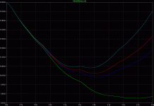
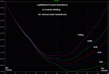
Here is Toms' graph of the MkII Lightspeed Attenuator input impedance from min volume to max with the load (input impedance) of the poweramp being 22k (not recommended), 62K, 100k and 1mohm
As you can see the input impedance as measured by Tom varies between 15k and 10k good enough for virtually any solid state output source and some tube output sources.
Power amp input impedance
Lime/yellow = 22k (not recommended by me)
Dark Blue = 62k
Red = 100k
Light Blue= 1mohm
Cheers George
Attachments
No problem, George.
Actually, since that was one of the ones that I only let run for 3 seconds, it's not quite right. The sim should run for 10 seconds, because of the time constants in the LDR model I was using..
I think that plot was for the volume knob being turned from min to max over the time on the horizontal scale.
The LTSpice simulation models are also posted. Someone should verify that I had it set up correctly and then re-run it with at least 10 seconds instead of 3 seconds.
EDIT: OK, I just found and re-ran the original simulation file, but with 10 seconds for the knob to traverse its entire range, instead of 3 seconds. Now, the input impedance is a tiny bit higher, everywhere.
Last edited:
EDIT: OK, I just found and re-ran the original simulation file, but with 10 seconds for the knob to traverse its entire range, instead of 3 seconds. Now, the input impedance is a tiny bit higher, everywhere.
Higher, even better thanks Tom. No need for buffers before or after the MkII Lightspeed Attenuator so long as sources are low around 200ohms or lower and poweramps are 47kohm (industry standard) or higher, as I have always preached.
Cheers George
Very interesting. At this impedance level, interconnects impedance effects are significantly reduced. So the source is really driving a constant load across the frequency range. Plus that lack of moving contacts in the signal path, this makes a good combination. Interconnects with single #24 core would work great here.
Very interesting. At this impedance level, interconnects impedance effects are significantly reduced. So the source is really driving a constant load across the frequency range. Plus that lack of moving contacts in the signal path, this makes a good combination.
Yes like I've been saying all along no need for buffers before or after, if you use real world sources with low output impedances (as it should be).
And you don't use amps that have low input impedance of less than (new benchmark thanks to Tom) of 33k or maybe even less looking at those graphs.
Cheers George
- Home
- Source & Line
- Analog Line Level
- Lightspeed Attenuator a new passive preamp

