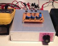
Here is my matching rig - it allows 3 LDR's at a time, (A,B,C on the back) with up to 12 current settings as shown(knob on lower right front).
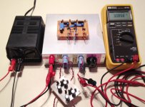
I use blue painter's tape to mark all the LED's first, and then put the readings into excel for sorting/graphing. Looking at a log-log plot of current and resistance for 2 units tells you instantly how good the match is.
The first wave of results was posted in the "other" current controlled LDR thread starting here -
http://www.diyaudio.com/forums/anal...-resistor-current-control-24.html#post2983854
This method is stable to very low uamps, and easily returns value in the Mohms. I agree you need to measure resistance higher than 10K, and very little is gained by taking a lot of data points in the 2-20mA range.
Attachments
I think the 2 x 10mA holes are a manufacturing defect as they are (on mine at least) both the same.
Cheers George
The documentation says that they are for matching the brightness of 2 LEDS at the same time (presumably by eye)
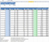
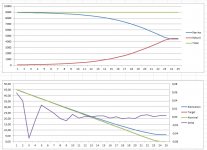
I am still working on my approach to match LDRs on the fly, and I have reached a nice average solution of matching on 24 positions, according to the image below

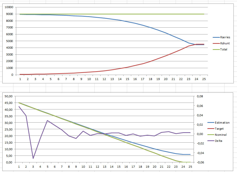
This seems to work nicely, but I am seriously considering jumping to a Tee topology.
We ll see...
I will post more very soon, once I get some actual measurments on the stability of my current sources
This seems to work nicely, but I am seriously considering jumping to a Tee topology.
We ll see...
I will post more very soon, once I get some actual measurments on the stability of my current sources
Attachments
Last edited:
I am seriously considering jumping to a Tee topology
excellent idea, Dimitri.
Years ago with the better quality analogue mixing desks, the volume pots were either t-pads, Pi-pads or more sophisticated attenuators because they just sounded better - not exactly cheap tho, especially the computer controlled motor driven ones.
With the LDRs, it may also be a 'better sounding' attenuator - George's original R + LDR morphed into the present LDR + LDR L-pad attenuator that is so widely used, regardless of the method of controlling the Leds - Uriah's varies the led's currents for adjusting the impedance loading and even Allan's "bridged method" uses the L-pad for it's attenuator..
With the T-pad, I can't remember if the resistance taper is the same (inversed) for both the series and shunt devices but this has been sorted before.
I do remember that as the attenuator became more sophisticated, the individual elements weren't as critical and this maybe of interests to those who have this obsession with attenuator channel balance in the other various threads.
Maybe there is a "downside" with the extra "T" resistor in series with the signal ....
There are many advantages in Tee. Sound is something that I have not yet tested, but what I particularly like is that it will allow keeping the impedance constant for both input and output.
So far, this is the issue that I am trying to find a proper solution to. Wether to used a matched tee (both output and input have the same impedance eg 9k) or to have a 9k input impedance and a low output one (eg 600 ohms).
The advantage of the tee topology is that it can keep those two constant.
The problem to designing for different impedances is that depending on the difference, there is a minimum attenuation. For example, if I go for 9k input and 600 output, the minimum attenuation has to be 17,63db (no small at all) which means that we have to sacrifice the upper end in the power of the amp.
You must not aim for a high output impedance/resistance.
Even 600r is a bit high.
I would target 100r, but that can't be obtained over the whole range of adjustment.
Personally, I would stick with the two LDR Lpad, because constant output impedance has no beneficial effect on the audio signal. It has a small beneficial effect on the RF effect.
Even 600r is a bit high.
I would target 100r, but that can't be obtained over the whole range of adjustment.
Personally, I would stick with the two LDR Lpad, because constant output impedance has no beneficial effect on the audio signal. It has a small beneficial effect on the RF effect.
Well as always, it s a give-take situation.
100R output impedance with 9k input, will mean 25,54db minimum attenuation which is very much
By the way, even with the Lpad topology on lightspeed, the output impedance reaches ~1,5k at some settings, so it s not all peachy there either.
Still only math at this point. Lightspeed sounds awesome in all the settings, so I might go with ~1k output impedance and try things out.
I do not worry too much about having a constant input impedance. One could design for a minimum number of, say, 9K, but not worry if it went to 30K or 50K.
I think the real concern is if the input impedance goes to say less than 1k ohms.
There may be designs out there where this happens")
As long as the output impedance stayed low, again below some target. And also aim for this to hold mostly in the "normal listening range".
I think the real concern is if the input impedance goes to say less than 1k ohms.
There may be designs out there where this happens
As long as the output impedance stayed low, again below some target. And also aim for this to hold mostly in the "normal listening range".
Good one.
But what if the power amplifier input that's downstream already has 1K series followed by 470 pF to ground, to filter RF?
Does the -3dB low-pass cutoff then go from their original 338.6 kHz down to 96.75 kHz? And that's assuming zero cable and other parasitic capacitance.
I don't believe in getting within a factor ten of the highest frequency that I want to not affect at all. So that 2.5k output impedance would be unacceptable, if my analysis wasn't flawed.
An output buffer would be one obvious solution.
I would need to look at how your input is actually implemented from jack to the high impedance active device, or if you have an input impedance curve up to 40KHz that would also work.OK, surprise me.
I have a nominal input Rin=100K. RF @ ~0.68us and LF @ ~90ms & 47pF @ RCA
I have a 10k volume pot. RF using 47pF
I have a Source with an output impedance of 200r.
The cable has ~ 50pF/m and is 3m long.
I have seen different implementations that create different input impedance curves.I would need to look at how your input is actually implemented from jack to the high impedance active device, or if you have an input impedance curve up to 40KHz that would also work.
the RF @ 0.68us is actually 1k0 & 680pF.I would need to look at how your input is actually implemented from jack to the high impedance active device, or if you have an input impedance curve up to 40KHz that would also work.
Now surprise me.
it's actually 680pF..............But what if the power amplifier input that's downstream already has 1K series followed by 470 pF to ground, to filter RF?
Does the -3dB low-pass cutoff then go from their original 338.6 kHz down to 96.75 kHz? ........
That combined with the 150pF of the cable and the 47pF at the RCA comes to a total capacitance of ~880pF.
The RF filter is worst case 2k5+1k & 880pF giving F-1db @ >= 52kHz.
But I actually have a pair of cascaded passive filters neither of which have zero source impedance nor do either have infinite load impedance.
My brain and my calculator need help in deciphering that combination.
But this is all worst case, to help Soong prove his point.
I would never accept a vol pot as having adequate drive capability for any cable + amplifier arrangement.
Are you talking about the same configuration as the MyRef input plus the RCA cap? Please be more specific.the RF @ 0.68us is actually 1k0 & 680pF.
Now surprise me.
You would be surprised how input impedance response over the frequency effects sound.
how much more specific than your first post do I need to be?Please be more specific.
I have a nominal input Rin=100K. RF @ ~0.68us and LF @ ~90ms & 47pF @ RCA
I have a 10k volume pot. RF using 47pF
I have a Source with an output impedance of 200r.
The cable has ~ 50pF/m and is 3m long.
and
the RF @ 0.68us is actually 1k0 & 680pF.
I know you know what the MyRef input is like, so is it that configuration plus the RCA 47pF cap? If not, show a schematic so that I know what exactly you are talking about. It should not be too difficult. There are so many ways of handling the input, I am not sure what you are looking for. You want me to design the inputs to that criteria? No way I have the time to do that. Generally you can design the input impedance to be flat over the frequency range, or you can let it drop at whatever frequency you like. The best for the DIYer is to make the drop as close to the interconnect as possible; In this situation, most likely the impedance at 20KHz will be half that of low frequencies. Why don't you play around yourself and discover what is best.how much more specific than your first post do I need to be?
Last edited:
- Home
- Source & Line
- Analog Line Level
- Lightspeed Attenuator a new passive preamp