Hi udaily. I am fairly new DIY audio, maybe only a couple years. I have succesfuly built a very good sounding LM3785 chip amp though. I am an electrical engineer by trade with experience digital electronics, like PIC programming.
I have made it to post 2000 in this thread now understand that these attenuators sounds better LDR/LDR instead of resistor/LDR. I just couldn't understand how putting the signal through the resistive side of the LDR sound better than a fixed quality resistor, but the thread speaks for itself.
I will do as you say and stick with the MKII version as this seems to be the desired choice of everyone on this thread.
Notice : All you US football fans, you have our direct telecast (or set your recorders)of our Australian Grand Final on your.
Live on Fox Sports Soccer Channel from 1:30am Eastern Time on Sunday, October 2
It's between my team the Manly Sea Eagles and the Auckland Warriors (a hopelessly outclassed New Zealand team) who open their mouths and stick their tongues out allot
You will see ball handling skill like you've never seen before, and bone crunching tackles without any whatsoever body armour.
Cheers George
LDR based input selection
How did your boys do George? Was the bonecrunching by your team") ?
?
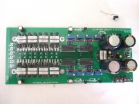
I promised a while back to show you guys how to do input selection with LDRs. I got the board done and working well. I will post a pic and then a link to discussion. I dont think its a transgression to speak about it here but this thread gets sidetracked so often, nice to keep it on track.
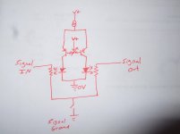
This is the general idea. Regulated voltage is put through a current source which supplies power to the LDRs. Regulated voltage is applied to a trimmer that turns on the transistors. By twiddling the trimmer you can balance the resistance of the LDRs so they are the same. By increasing the voltage you can lower the resistance of both at the same time.
ON means both LDRs turn on full force at 40R each for a series total of 80R and the relay is open.
OFF means that both LDRs have 25Megohm or more resistance and the relay has less than 5R. Its an optocoupler relay to keep with the theme.
How did your boys do George? Was the bonecrunching by your team
?I promised a while back to show you guys how to do input selection with LDRs. I got the board done and working well. I will post a pic and then a link to discussion. I dont think its a transgression to speak about it here but this thread gets sidetracked so often, nice to keep it on track.
This is the general idea. Regulated voltage is put through a current source which supplies power to the LDRs. Regulated voltage is applied to a trimmer that turns on the transistors. By twiddling the trimmer you can balance the resistance of the LDRs so they are the same. By increasing the voltage you can lower the resistance of both at the same time.
ON means both LDRs turn on full force at 40R each for a series total of 80R and the relay is open.
OFF means that both LDRs have 25Megohm or more resistance and the relay has less than 5R. Its an optocoupler relay to keep with the theme.
Attachments
Sure did, the Manly Sea Eagles surgically beat the New Zealand Warriors 24-10
Highlights here if you want to watch them.
NRL 2011 Grand Final Highlights: Sea Eagles V Warriors - YouTube
Cheers George
Highlights here if you want to watch them.
NRL 2011 Grand Final Highlights: Sea Eagles V Warriors - YouTube
Cheers George
My LDR test rig
Thought I would upload my LDR matching rig. Haven't received my LDRs from Uriah yet, but I have put some normal LEDs in just to test that the rig works.
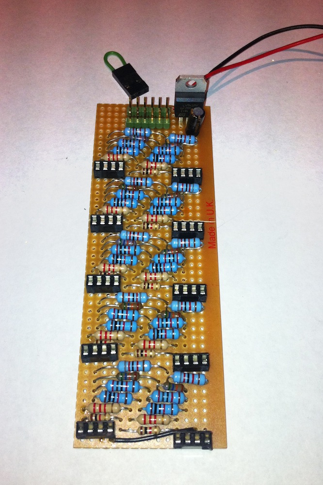
I have added some annotation to the second image. The output of the 5 volt regulator is connected to the top row of header pins. There are 10 hand matched resistors connected to each of the 6 pins on the second header. You can't see it in the picture, but each 4 pin socket (an eight pin socket cut in half) on the board has the two left pins connected together and the 2 right pins connected. (I could have used a 2 pin socket, using a 4 pin holder was easier to assemble). These holders are where you sit each LDR. The +ve terminal of the 4 pin sockets has the ends of 6 different value resistors connected to it. To select what value resistance you want to apply to the LDRs, you simply insert the resistor jumper into one of the six positions on the top of the board. (From the common 5 volt supply to one of the pins on the second header)
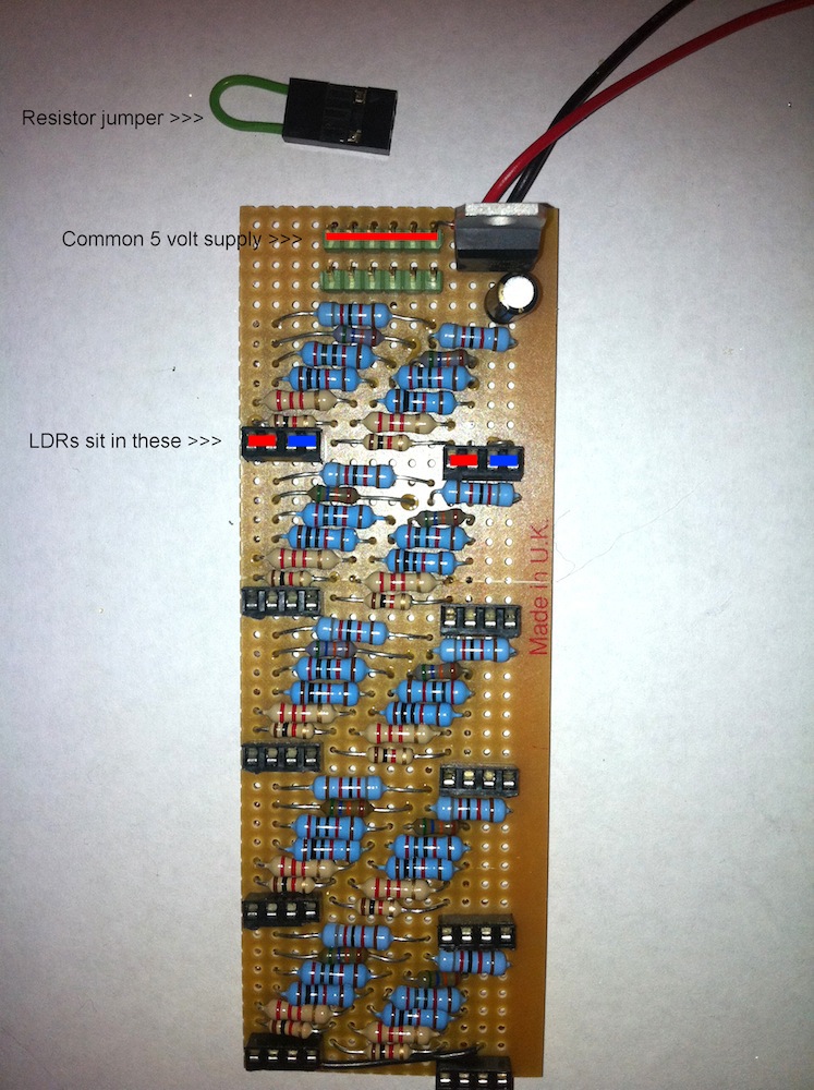
It probably took me longer to match the resistors than it did to actually make the board. Hopefully the board will make easy work of matching my LDRs
Thought I would upload my LDR matching rig. Haven't received my LDRs from Uriah yet, but I have put some normal LEDs in just to test that the rig works.
I have added some annotation to the second image. The output of the 5 volt regulator is connected to the top row of header pins. There are 10 hand matched resistors connected to each of the 6 pins on the second header. You can't see it in the picture, but each 4 pin socket (an eight pin socket cut in half) on the board has the two left pins connected together and the 2 right pins connected. (I could have used a 2 pin socket, using a 4 pin holder was easier to assemble). These holders are where you sit each LDR. The +ve terminal of the 4 pin sockets has the ends of 6 different value resistors connected to it. To select what value resistance you want to apply to the LDRs, you simply insert the resistor jumper into one of the six positions on the top of the board. (From the common 5 volt supply to one of the pins on the second header)
It probably took me longer to match the resistors than it did to actually make the board. Hopefully the board will make easy work of matching my LDRs
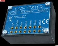
Or you could just use of these with a multimeter which gives more than enough from 1mA to 50mA, which is what I did early days, before I built a more elaborate way of doing it.
PS Thanks Theophile
Cheers George
Attachments
Finished matching
Received the LDRs for Uriah today and started matching them with my rig. The rig holds 10 LDRs at a time and with the jumper on the top of the board, I can select 1K, 2.2K, 10K, 20K, 56K and 82K to be put in series with the LED side of the LDRs.
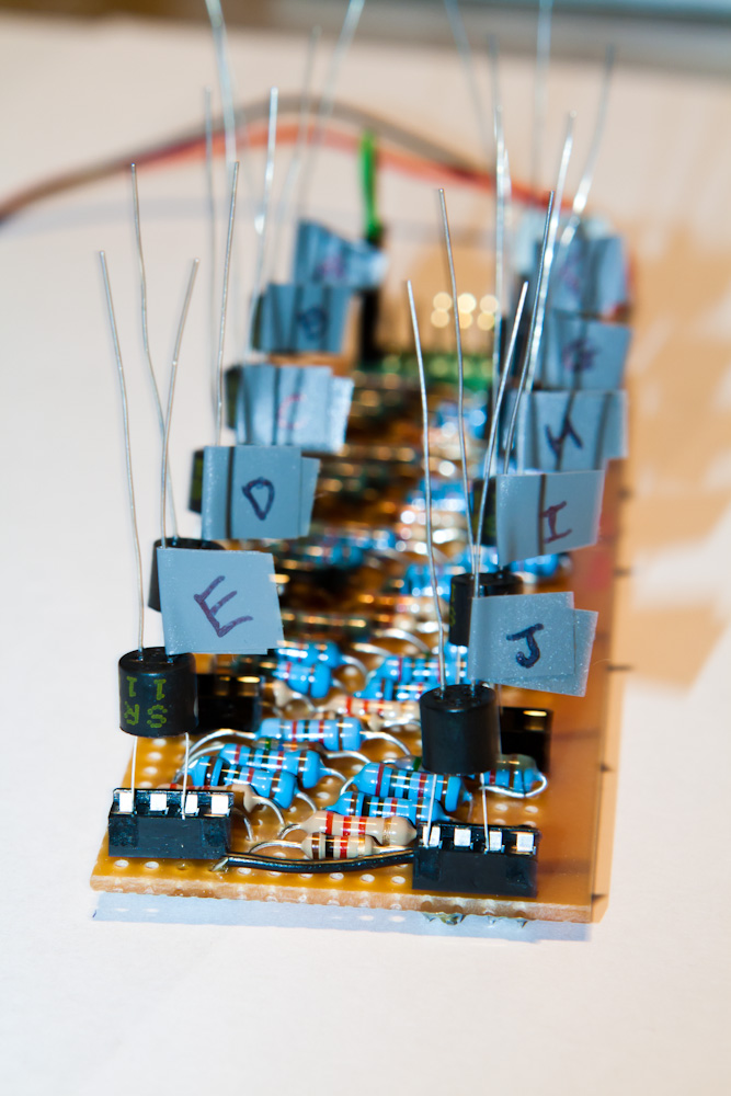
Here is a graph of the results.
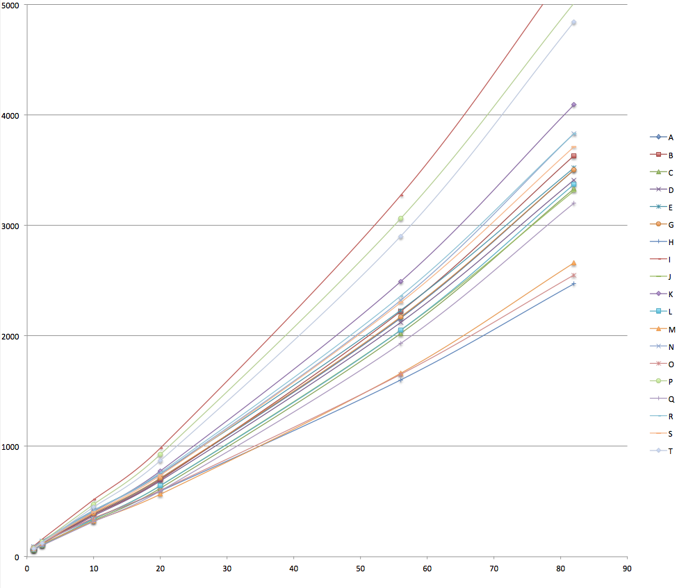
As you can see, there is a big difference between the LDRs. (By the way, F was removed from the graph because it was so different from the rest).
Out of th2 20 LDRs I have 2 good pairs, and maybe a couple other 'not so good' pairs.
Here are the resistance values for my 2 pairs:

They seem pretty close
Received the LDRs for Uriah today and started matching them with my rig. The rig holds 10 LDRs at a time and with the jumper on the top of the board, I can select 1K, 2.2K, 10K, 20K, 56K and 82K to be put in series with the LED side of the LDRs.
Here is a graph of the results.
As you can see, there is a big difference between the LDRs. (By the way, F was removed from the graph because it was so different from the rest).
Out of th2 20 LDRs I have 2 good pairs, and maybe a couple other 'not so good' pairs.
Here are the resistance values for my 2 pairs:
They seem pretty close
Q and C for shunt? Is this because A and G are a closer match and that's better for the series resistors?
It was interesting matching the LDRs, don't know how you do hundreds in a day Uriah, would probably drive me crazy.
When people say that they match there LDRs to 1dB, what do they mean, how can I get a dB from 2 resistances? Do I use this equation:
dB = 10 x log10 (resistance1 / resistance2)
or is this equation only for power?
Q and C for shunt because they match best at low resistances and you will be listening, I am assuming, at low to mid volume most of the time where these resistances will be in shunt. Series are the other two because they match best at high resistance where series will be in low and mid volume listening.
Your equation is close but its a log20 equation which I dont recall the rest of. Probably can find it in wikipedia. Either way it doesnt matter because these are your best 2 pair. Who cares if they are 1dB or .1dB, this is what you have.
Your equation is close but its a log20 equation which I dont recall the rest of. Probably can find it in wikipedia. Either way it doesnt matter because these are your best 2 pair. Who cares if they are 1dB or .1dB, this is what you have.
Thanks Uriah.
I don't necessarily want to work out the dB difference, but I was curious as to how it is worked out. I found a couple of equations for dB power and dB voltage. The dB voltage equation is : dB = 20 x log10 (v1 / v2)
I should hopefully get ordering my parts this week
I don't necessarily want to work out the dB difference, but I was curious as to how it is worked out. I found a couple of equations for dB power and dB voltage. The dB voltage equation is : dB = 20 x log10 (v1 / v2)
I should hopefully get ordering my parts this week
http://www.diyaudio.com/forums/analogue-source/154210-mpp-134.html#post2184627
Considering different power supply options? Read this.
Considering different power supply options? Read this.
- Home
- Source & Line
- Analog Line Level
- Lightspeed Attenuator a new passive preamp