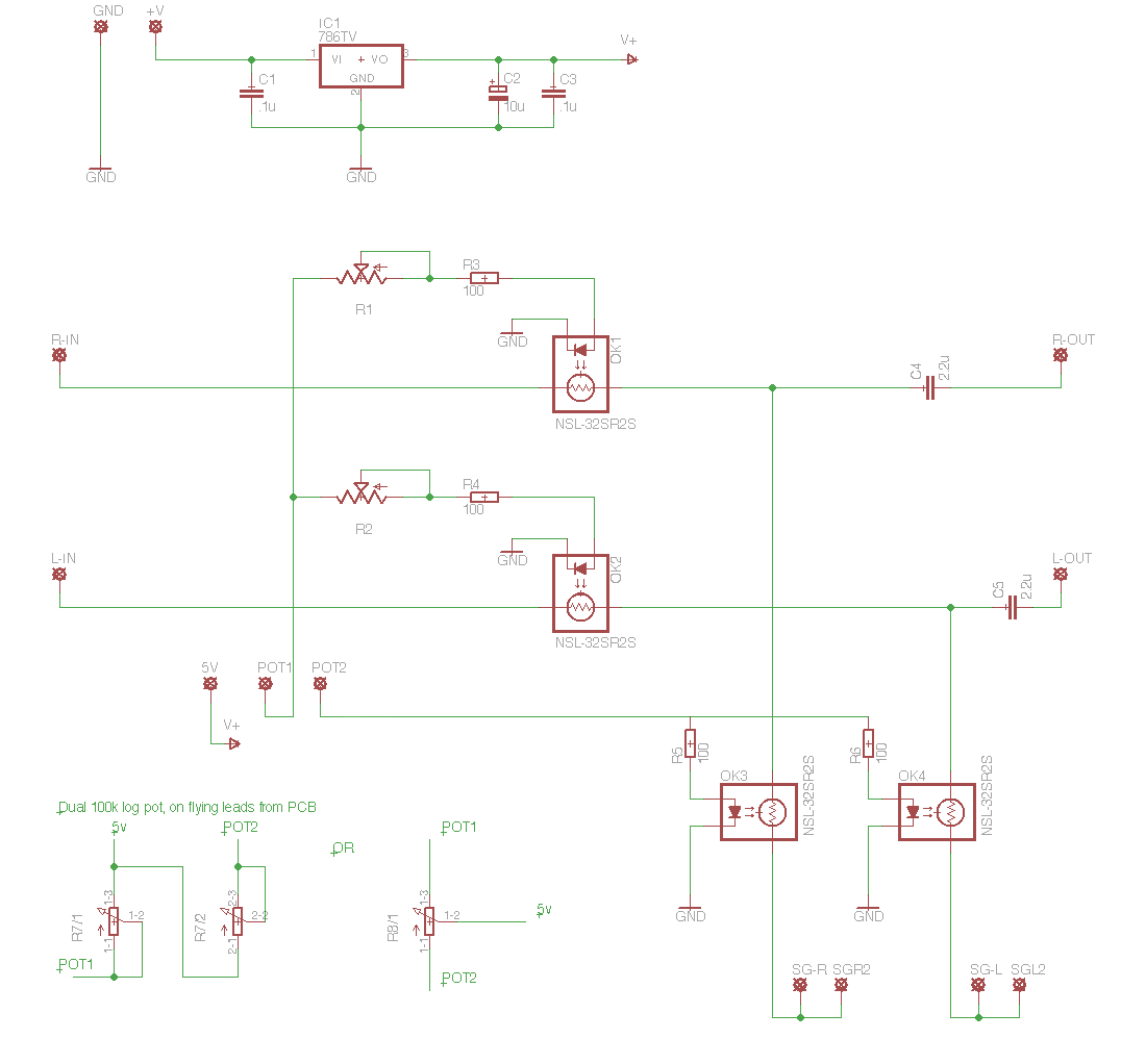
Thanks George, your schematic in post #4240 is the one in which I have created in Eagle.
Obviously this design only really needs 2 matched pairs, but as you said, quad matched will obviously be better. As for the 5 volt supply, can this be on the same PCB as the LDRs? or is it best to keep it separate for noise?
You also show in your drawing that the feed to the 7805 is 9 - 18v, these have a max input of 35v according to the datasheet, so would my 25 v be OK, if the regulator was bolted to my heat sink along with the amp chip?
Your MKII circuit shows only 1 100K log pot, this should work with the MKI schematic also shouldn't it? 5v to the wiper, one end to one pair of devices and the other to the other pair.
Same as for both, one trimmer only on the louder channelThanks George, your schematic in post #4240 is the one in which I have created in Eagle.
Obviously this design only really needs 2 matched pairs, but as you said, quad matched will obviously be better. As for the 5 volt supply, can this be on the same PCB as the LDRs? or is it best to keep it separate for noise?Supply for the led's is totaly isolated from the ldr's so yes it can be on the same board
You also show in your drawing that the feed to the 7805 is 9 - 18v, these have a max input of 35v according to the datasheet, so would my 25 v be OK, if the regulator was bolted to my heat sink along with the amp chip?Yes the more you sink the hotter it will get
Your MKII circuit shows only 1 100K log pot, this should work with the MKI schematic also shouldn't it? 5v to the wiper, one end to one pair of devices and the other to the other pair.
Cheers George
Last edited:
Thanks George. In your schematics, you have signal GND and the 5v power GND together, would it not be better to keep them separate, like this:
Also, just looking at the LM7805 regulators, because the current this circuit uses is so small (not much more than 50mA) and the regulators are rated at 1A or some at 1.5A output, it shouldn't get very hot, especially if it connected to the heat sink.
Also, just looking at the LM7805 regulators, because the current this circuit uses is so small (not much more than 50mA) and the regulators are rated at 1A or some at 1.5A output, it shouldn't get very hot, especially if it connected to the heat sink.
Last edited:
Another quick question. What is the need for a series and a shunt LDR?
Could you not substitute the series LDRs for (1K resistors for example) and then alter the resistance of the shunt LDRs, therefore only needing 2 devices?
I understand in a normal input pot setup, it is 'seen' by the previous piece of audio equipment as the total of resistance of the pot and this is always the same. But surely using 2 x LDRs, you are not guaranteeing a constant input impedance, are you?
Again, sorry if these questions have been answered previously, I have only just got to post #951")
Could you not substitute the series LDRs for (1K resistors for example) and then alter the resistance of the shunt LDRs, therefore only needing 2 devices?
I understand in a normal input pot setup, it is 'seen' by the previous piece of audio equipment as the total of resistance of the pot and this is always the same. But surely using 2 x LDRs, you are not guaranteeing a constant input impedance, are you?
Again, sorry if these questions have been answered previously, I have only just got to post #951
Another quick question. What is the need for a series and a shunt LDR?
Could you not substitute the series LDRs for (1K resistors for example) and then alter the resistance of the shunt LDRs, therefore only needing 2 devices?
I understand in a normal input pot setup, it is 'seen' by the previous piece of audio equipment as the total of resistance of the pot and this is always the same. But surely using 2 x LDRs, you are not guaranteeing a constant input impedance, are you?
Again, sorry if these questions have been answered previously, I have only just got to post #951
I believe that was Georges mk1 version. The mk2 and better sounding ? version uses the four ldr's. This thing does sound good; just gets out of the way of the music.
Hi Marra. The drawing I have done is a copy of the MKI version (post #33), the MKII version uses a single pot and one trimmer I believe.
Are there any reasons why having a varying impedance (using a fixed resistor and an LDR) other than a more steady input impedance (series/shunt setup) would benefit. Does audio equipment NEED to 'see' a fixed impedance? If it doesn't, then wouldn't a single LDR and resistor on each channel be easier to implement and give a smoother curve, as you are only adjusting one resistance, not 2.
Are there any reasons why having a varying impedance (using a fixed resistor and an LDR) other than a more steady input impedance (series/shunt setup) would benefit. Does audio equipment NEED to 'see' a fixed impedance? If it doesn't, then wouldn't a single LDR and resistor on each channel be easier to implement and give a smoother curve, as you are only adjusting one resistance, not 2.
Last edited:
Thanks George. In your schematics, you have signal GND and the 5v power GND together, would it not be better to keep them separate, like this:
Also, just looking at the LM7805 regulators, because the current this circuit uses is so small (not much more than 50mA) and the regulators are rated at 1A or some at 1.5A output, it shouldn't get very hot, especially if it connected to the heat sink.
Sorry the powersupply is not grounded to the chassis or signal. It makes no discernable difference if it is, I just let it float because it can, as wall warts have no earth and the led and it's powersupply have no electrical connection to chassis or rca earth.
Cheers George
Another quick question. What is the need for a series and a shunt LDR?
Could you not substitute the series LDRs for (1K resistors for example) and then alter the resistance of the shunt LDRs, therefore only needing 2 devices?
I understand in a normal input pot setup, it is 'seen' by the previous piece of audio equipment as the total of resistance of the pot and this is always the same. But surely using 2 x LDRs, you are not guaranteeing a constant input impedance, are you?
Again, sorry if these questions have been answered previously, I have only just got to post #951
There are many advantages mentioned for the MKII over the MKI, but the MKII is much harder and costlier to make, otherwise I would have stuck with the MKI.
Cheers George
Cheers George
Hi portreath
Yes there will be a smile to the resistance curve. Its alright. There is not an advantage to it, its just the way the LDRs are. There is also no disadvantage. If you adjust the series LDRs to still keep the max current low enough to do no damage to the LDRs/LEDs then you can fool with the voltage to the LED side and you can adjust Rtot of your LDR attenuator to better match your system. We used to suggest 47k as min input impedance of your amp but by using this tactic I have successfully used much lower input impedance amps. Still no excuse for an amp having a 10k input impedance when the designer has control of that but sometimes thats the situation we are faced with so we must adjust Rtot and we must have a source that can push the lower Rtot. If we do then the fact that Rtot changes really has no effect on listening.
Uriah
Thanks for your reply udaily.
What would happen if you had an LDR as the series resistor and a fixed resistor as the shunt? Has this been tried?
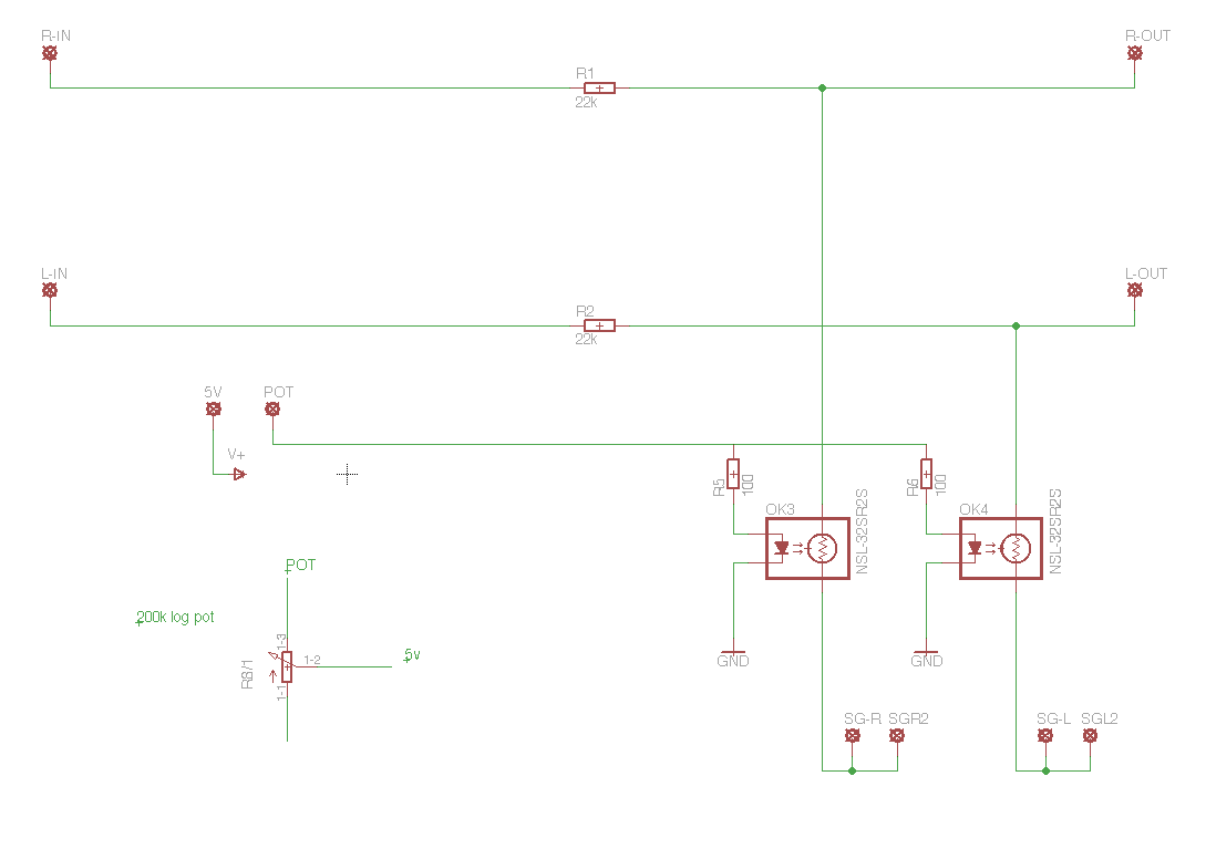
I am planning on making using a Lightspeed MKII style attenuator, (or an attenuator with 22K series res and LDR shunt resistor) on the front end of a LM4780 chip amp with a 22K input resistor, this should work OK, right?
What would happen if you had an LDR as the series resistor and a fixed resistor as the shunt? Has this been tried?
I am planning on making using a Lightspeed MKII style attenuator, (or an attenuator with 22K series res and LDR shunt resistor) on the front end of a LM4780 chip amp with a 22K input resistor, this should work OK, right?
Thanks for your reply udaily.
What would happen if you had an LDR as the series resistor and a fixed resistor as the shunt? Has this been tried?
I am planning on making using a Lightspeed MKII style attenuator, (or an attenuator with 22K series res and LDR shunt resistor) on the front end of a LM4780 chip amp with a 22K input resistor, this should work OK, right?
1: you need the signal to go to ground to get volume low. Fixed shunt resistor is going to give you a small volume range with most of it being real loud.
2: It will work. How well it works depends on your source output impedance and the value you choose for your series and shunt LDRs as their max value.
I suggest you follow George's schematic to the letter and start with that. Its a good design and works well with chipamps. You can replace the 100R series resistors with trimmers and the 7805 with an LM317 circuit if you want to mess with the max resistance values of series and shunt later.
Uriah
Hi again Udaily. Thanks again.
Please can you tell me of anywhere to buy the Silonex LDRs in the UK?
I have an account with Farnell, but they only sell NSL-32SR2, not the NSL-32SR2S!
RS sell the S versions, but are subject to a £10 extra charge on an order due to them being an 'Extended Range' item.
Is there any point in trying to match using NSL-32SR2, or should I simply buy a matched pair from you? If I were to buy a matched pair from you, how much is the postage to the UK?
udaily, I have read a another 50 or so pages of this thread and have a question. In post #1852, you say that with a resistor on the LED side of the LDR, your average reading is about 3 - 3.5K on the resistance side. With 100K, you say you got 6.2K on the other side.
If I were to experiment with a fixed resistor (maybe 22K) and a shunt LDR, Would I have to use a very large pot, as surely with 100K pot, I may only have 6K of of resistance on the output side, therefore my signal (say 1v peak) would be dived across the 22K resistor and 6K LDR. 1v x 6 K / (22K + 6K) = 0.21v on it's loudest setting.
Is this correct?
Thanks again
HI,
You don't need the "s" series. They are just presorted SR2's. The sorting doesn't help much and sure doesn't sound different.
If you want to consider buying from me please pm me so we don't add more clutter and off topic discussions here.
I think you should be shooting for a series below 10k and if your source can push it then even lower to 5k-6k. That's assuming you should be using a series resistor. What's the attraction to doing it different than the 2000 posts you read are suggesting? If you contact me off this thread I will shoot you a lightspeed build manual that you could use with your own ldrs and even your own PCB....or you could read my project on diyaudioprojects.com which will help a lot.
It's pretty apparent you are new to DIY audio and we are all here to help you. I think yhe best advice I can give you right now is to build first like George says.... Then understand the circuit and why its working how it does....then play with the circuit one small change at a time if it suits you at that time. The paths you are suggesting truly make no sense and won't yield a sound as good as the basic circuit.
If you go basic... I will help you as much as you need. I will also help you if you alter it later.
- Home
- Source & Line
- Analog Line Level
- Lightspeed Attenuator a new passive preamp