Alazira. I have added 20R as you suggested. That gives me a fully useable sweep of the pot.
Puffin,
That's good to know. I does make me wonder if the value is less important than just adding a second resistor.
Garrett
I experimented with a lot of different values. Oddly enough 1K made very little difference, 10R too much attenuation, 20R getting there. I think I will try 30R tomorrow.
At the moment most of my listening is done at the 12oclock position. I would prefer it to be 10oclock.
At the moment most of my listening is done at the 12oclock position. I would prefer it to be 10oclock.
Eh, sorry can I just ask here.... are you adding the 10R, 20R or 30R in the 5V feed to the pot or are you adding a resistor before each LDR (or even pairof LDRs)?
Fran
Hi Fran,
I added a 100R to the 5V feed and kept the 100R into the LDRs (for a total of two resistors in series, well, actually three if you consider the potentiometer). I am beginning to wonder how much difference the value makes though.
Garrett
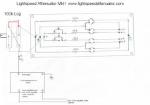
Fran. It is really simple. Poor picture, but you just connect the resistor between the pins 3 L&R
An externally hosted image should be here but it was not working when we last tested it.
let's assume that we have V+ = 5V.
Vf = 2V
R from 5V = 100r
R to each LED = 100r.
What is the maximum current that can flow to any LED in worst case conditions?
Imax = [ V+ - Vf ] / [ 100r + 100r ] = 15mA
One cannot overload any of the LEDs using these values for the resistors. The pots can be any value from 0r0 to 10M and the LEDs will work.
Fine tuning of these added resistors may well achieve a nice attenuation rate in the pot rotation. Keep trying and report back.
OK, I probably need to try this and see about bringing the range up. right now 9oc is about as loud as I ever listen. Would be lovely if that was 12oc.
Otehr than that I have it up and running and have been pretty impressed. Need to spend a bit more time now critically listening to it.
Fran
Otehr than that I have it up and running and have been pretty impressed. Need to spend a bit more time now critically listening to it.
Fran
Nope, I must be doing something wrong!!
I wired in a 10K pot in line with the 5V feed to the 500k pot. Makes absolutely no difference what I set the 10k pot at.
Looking at your pics puffin it seems you have the resistor between the 2 feeds out to the series/shunt LDRs, kind of tying the 2 legs together - is that correct? Would be real neat for me to have a more useable sweep on the pot. So at low value resistor, both series and shunt would see the same voltage? and as the resistance went higher, the voltage would differ more. Am I making any sense???!
****************************************
On the plus side, the lightpseed sounds very good. Spent a bit of time tonight with it and it sure does sound really good. Mine is destined for a B1 buffer, but I'm wondering why would I bother. It really does sound good on its own. I will have to try it in the B1 though, seeing as a few have recommended it highly.
***************************************
3rd thing!!! When I made mine frst I used Uriahs PCB layout. But I made a dogs dinner of etching - basically I ended up with a mirror image of what I should have had.
Anyway, heres what I ended up with..... a balance control!! So it seems to me that if someone wanted a really transparent balance control, then this might be something worth checking out.
Fran
If his pot is wired as per my diagram, then his resistor (in red) is wired from the 5vdc feed to both channels of the shunt leds only.
What is happening in this case is that the circuit is going slowly back to Lightspeed MkI configuration, which gives less total range to the control of the volume.
Cheers George
What is happening in this case is that the circuit is going slowly back to Lightspeed MkI configuration, which gives less total range to the control of the volume.
Cheers George
Attachments
Last edited:
What is probably also confusing me is that I am using a single gang pot rather than the stereo ones above. So in my case I think all I would need to do is add a resistor between the 2 feeds out to the series and shunt LDRs, ie between the 2 output legs. That mimics whats in your drawing george, right?
Might try that tomorrow night! I'm gone back now to set up a nicer power supply - I'm gonna use a teddyreg on it. Have the PS more or less ready now to go, so I only need to fit the lot into the box that my B1 is in.
*********************************
I spent some more time tonight back with the b1 again and I think that maybe the b1 has a shade more kick to it. Now, look, I have to add in there that this is a pretty tiny difference, and I couldn't swear to it right now. I only went back because I started saying to myself, why bother including the B1 at all! I had pretty mixed experience with passive attenuators before (ie not bad, but big improvement when you swap to a decent active) but the lightspeed is very impressive.
I will go ahead and add it into the b1 - if only for experimentation purposes. I hope I get the best of both! Thing is - even if I get the worst of both, it will still be bloody good!!
Cheers!
Fran
Fran,
Not saying dont do it, but I remember someone posting or emailing me that they had a not so great review of the teddy reg with the Lightspeed. I think its another reg that needs a decent load on it. Why not try though? A teddy reg is a nice thing to have if its not used with this anyway.
Uriah
Not saying dont do it, but I remember someone posting or emailing me that they had a not so great review of the teddy reg with the Lightspeed. I think its another reg that needs a decent load on it. Why not try though? A teddy reg is a nice thing to have if its not used with this anyway.
Uriah
Yeah, I have a 1K load resistor on the output of the teddyreg just to make it work a bit. Output seems rock solid. The only downside is that it doesn't have a very low output impedance, but that may not matter here. Anyway, I can try it and see!!
It will be easy to remove it, but initial tests seem to suggest not much difference between using it/not using it.
BTW, it may have been me that posted. I had done my own PCB layout waaaaay back that had a teddyreg as a plugin module, but that didn;t work. After more than one person telling me to just air-wire it, I'm finally convinced that this is probably the way to go!!!
**************************
Am I correct in thinking that the resistor should go between the 2 feeds out to the series and shunt LDRs?
Fran
OK, I tried a 10k pot across the 2 legs to the series shunts: made no difference other than make it louder at low volumes (lower the resistance the louder it got). Also tried it in series with the 5v supply line: no difference. So to sum up.... no difference!
But to other news:
Lightspeed installed in B1. Listening awaits!!!
Fran
But to other news:
Lightspeed installed in B1. Listening awaits!!!
Fran
PWM would and does work fine. I have one battery power and one PWM. PWM sounds fine but battery sounds better, however, it is also crafted differently so I am not sure if its the power supply or the assembly that sounds better.
Now I am talking about supply by PWM not control by PWM. I have not tried to control the brightness by varying with PWM and what I have read is only negative things because of the switching. Others have said that you can snub the LDRs to remove any switching noise. To me, it seems that snubbing them would get rid of ringing when they are switched but they are still going on and off very fast. I would think this would create some noise but you probably wouldnt hear it and this is noise in the LED not in the resistor since the LDR is an optoisolator.
I think any solution to power them is worth a try. Its nearly the only thing you can tweak in the circuit so why not tweak it? Its also easy enough to build a small linear supply and small battery supply as well as constant current sources to try several different supplies and find what sounds best to you.
So hows that for answering without answering? This question is one of the big contentions on this thread and I have not read anyone who satisfactorily came to a conclusion by testing and measuring between different supplies.
Uriah
- Home
- Source & Line
- Analog Line Level
- Lightspeed Attenuator a new passive preamp