How many mA is your consumption? I know better than battery, liittle shunt with 3 components.
Andrew, is that 30mA max for two channels?
let's assume that we have V+ = 5V.
Vf = 2V
R from 5V = 100r
R to each LED = 100r.
What is the maximum current that can flow to any LED in worst case conditions?
Imax = [ V+ - Vf ] / [ 100r + 100r ] = 15mA
One cannot overload any of the LEDs using these values for the resistors. The pots can be any value from 0r0 to 10M and the LEDs will work.
Fine tuning of these added resistors may well achieve a nice attenuation rate in the pot rotation. Keep trying and report back.
Andrew, is that 30mA max for two channels?
the 15mA current limit due to 3V drive and 100r + 100r in series is the highest current to any single LED.
If two LEDs are in parallel and each has a 100r in series then the worst case current becomes 3000mV / (100+50) =20mA shared between the two parallel LEDs, i.e. worst case of a two channel set up with a common 5V + 100R supply is 10mA per LED.
If one wants a slightly wider range of attenuation one may want to look at the possibility of reducing the series resistors to ~82r or maybe as low as 68r.
3000 / (68 + 34) = ~30mA total or 15mA per LED
If one leaves the lightspeed on 27,7 and leaves the volume setting at max or min then two LEDs will be passing 15mA each for 6000 to 8000hrs per annum. That could be a good reason for not using 56r series resistors.
Last edited:
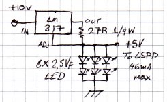
Its a CCSed mini shunt idea. OK, it would be 3 components if it was under 10mA so a NJFET could be the CCS and one string could take the current, still simple though for 46mA max. If you don't have 2.5Vf LEDs in hand, it can be lifted by using a diode between the LEDs and earth. Also a 470uF capacitor from +5V output to ground can be added if proves subjectively beneficial. It just needs 8-10V rectified and capacitor filtered DC for input.
Attachments
Aging Issues with LEDs and LDRs
Is anyone worried about aging effects which afflicts devices of this type. All LEDs show a decrease in light output over time. I don't know what the LDRs do over time, but here is what PerkinElmer has to say about these devices:
"Life expectancy of an AOI is influenced both by the input and output
devices. Isolators which use an LED have long life since LED lifetimes
are long: 10,000 to 200,000 hours, depending on the application. LEDs
normally show a decrease in light output for a specified bias current as
they age.
The photocell output elements in AOIs show an increase in output
resistance over time as they age. With a continuous input drive current
and with voltage bias applied to the output, the output resistance will
generally increase at a rate of 10 percent per year. The aging rate is
lower with intermittent operation. Figure 5 shows the trend line for
output resistance under typical operating conditions. Other AOIs using
different photoconductive materials show similar trends..."
http://optoelectronics.perkinelmer.com/content/RelatedLinks/Articles/ATL_analogoptoisolatorB.pdf
I know about the Perkin Elmer ones, I found the Silonex to be a better one (NSL32SR2S) for this application, they told me they have 200,000hrs to 300,000hrs use, if on for 24/7 that equates at the minimum 200,000 to 22years!!!, and if run at half power (lets then give them 300,000hrs) as I state in the instruction that come with the production Lightspeed Attenuator, that equates to 34 years!!!!!!! life expectancy.
The hundreds that I have built to date, the oldest are over 5 years old are still going as strong as the day they were built.
Cheers George
The hundreds that I have built to date, the oldest are over 5 years old are still going as strong as the day they were built.
Cheers George
George, I am referring to the aging rate, not the lifetime. What does Solinex specify for aging? I guess I'll have to give them a call to find out.
Have you measured the resistance transfer function of an LDR over extended periods of time?
I'd like to build this, but I think that long term, this design needs to be tweaked periodically, or there needs to be some form of automatic adjustment mechanism.
roco
Have you measured the resistance transfer function of an LDR over extended periods of time?
I'd like to build this, but I think that long term, this design needs to be tweaked periodically, or there needs to be some form of automatic adjustment mechanism.
roco

Sounds like I will have to buy a few of these and measure them over a 1-2month period. This is pretty easy to do.
In the meantime, I'll see what the manufacturer has to say about the stability of LDRs.
Oh, btw, it's not that I intend to use this forever. It's just that I'm trying to decide between this and a passive preamp with resistor arrays and relays...I think this is the best solution.
George, I am somewhat surprised that you have no hard data to share on aging after working on this for so long.
George, I am somewhat surprised that you have no hard data to share on aging after working on this for so long.
This is the hardest I can supply, I can only go back to when I first used them ( Silonex NSL32SR2S) over 5 years ago my prototype, it was the first Lightspeed to use them and is still 100% to spec today and still in use after 44,000hrs of being on.
When I first did the Lightspeed Attenuator some 30 years ago, yes the LDR's of brands available then were a problem, they were made from different materials and were much larger, they were used in lightmeters in Nikon and Pentax and other cameras that I use to repair (Hifi was my hobby/obsession then) these were unreliable and later similar were then used by Melos in their flagship SHA Gold Reference preamp with the ldr pot called the Porzilli Potentiometer after Mark Porzilli who designed the SHA-Gold Reference, all these came back within one-two years with problems to Melos in the late 90's I think this could of been part of the reason they went broke. But the new Silonex combo LDR/LED are so much better, I believe are as stable as you could ask for when the 4 are matched to start with.
Cheers George
George, I see that you are mentioning very often lately that the 'sorted' are a better LDR to use. I have to disagree here and often discourage people from purchasing the sorted and to go for the unsorted. The LDRs are in fact the exact same LDRs except that for literally a few seconds they have had voltage applied to them and have been tested for resistance. The problem here is that you can gain nearly zero knowledge about the LDR in question if voltage is applied for a few seconds. I have to have an LDR powered up for 15 minutes minimum before the dynamic resistance slows down. So, after less than a minute Silonex takes a reading that is between 100 and 200 ohms. None of us use 100 to 200 ohms and although that reading is meant to be an indication of how the LDR will act at higher resistances.. it just isnt so. Readings at any level have no relationship to how a reading will be at a higher resistance in series. The matching still has to be done and at no time have I measured 100 ohms and thought "Oh, this will probably be a great match with that other one that measured 100 ohms but had a second reading of 10,000 Ohms." I have said that to myself after 3 readings were taken and known that the 4th reading would match with another LDR that had 3 other similar readings but never with just one reading. The only advantage to the sorted LDRs is for Silonex and the advantage is cost. They cost a lot.
3.07 each so if a guy bought 20 to get a match he is paying 61.40. OR he could buy 20 and probably get a match with the unsorted for 2.29 each for a grand total of 45.80.
I am tempted to try the NSL-32 which is a 500OHM at 20mA LDR that is capable of 40mA through the LED and only costs 1.78, or 35.60. Its is also made out of the same resistive material and I dont see how it could sound any different.
Proof positive is in my matching. I have attached a pdf file. It includes all matches found in a test of 549 LDRs. This is with unsorted LDRs and I was very pleased with the results. Strangely enough these LDRs need to be controlled with a 500k but the results were nothing short of spectacular and my last purchase of sorted LDRs was my first batch of LDRs that I tried matching for my own Lightspeed.
I agree with what you have been saying recently about all 4 matching well. As you can see its not so hard to get 4 very close to each other. The only advantage is a more stable input impedance but I have found that if you build a circuit where you can vary the input impedance yet keep the same volume it is audible.. the difference in impedance and lower impedance, on my amp, just sounds better and better.
So I guess what I am saying is I dont understand the push for the sorted LDRs. I dont think it makes it easier for even the guy buying a small quantity.
Uriah
Attachments
Last edited:
I totally agree, the sorted are not so close either, but for me they have been closer than the non sorted, more importantly I get the same batch letters (A,B,C,D,E or F) when I ask for them when ordering the sorted, they don't do that for me if I order the non sorted, and in here lays the matching secret I believe.
Cheers George
Cheers George
Last weekend I put together a balanced version of the Lightspeed. It's a crude assembly done to test things out. I followed George's simple plan and it worked perfectly well, even though it has eight LDRs altogether instead of four, and all the LDRs are in the open, etc. The test was to see whether it would work into 7-meter interconnects to the tube power amps. My CD player has a built in volume control and will drive the amps directly with no problem but I needed a volume control for the phono stage.
I tried the CD player first, with the Lightspeed at the amplifier inputs and then with the Lightspeed at the other end of the interconnects near the CD player. I heard no difference. And that means I can use the Lightspeed near the sources in a box combined with input switching. The sound with the Lightspeed seemed a bit smoother than it was with the CD player connected directly to the amps . No complaints.
After that I tried the Lightspeed with the phono stage. The sound is impressive, maybe even better imaging than with the tube line stage I had been using. Certainly it sounds better than when the tubes in the linestage got tired.
After reading the Lightspeed discussion for months I chose to avoid complication. If the LDRs might drift from age, which seems unlikely, then I'll just turn the volume control up a bit. If the LDRs don't last forever, then I'll just remember how much cheaper they are than a new set of vacuum tubes.
The LDRs were supplied by Uriah Dailey. He's all set up to do the matching properly, and I'm not. My trial setup had no trimmers and I'm tempted not to use any in the final version. This indicates that Uriah did a great job of matching the devices. The power supply I found in the recycling area of our apartment building. I made a 5v regulator according to George's schematic, and used a 100k pot with 100 ohm resistors ahead of the LEDs. I had intended to build in a switchable resistance to put the LDRs at medium value for standby, instead of turning the pot to midway as George suggested. However, workable volume has the pot set about midway so I won't bother with a standby arrangement. What I'm thinking about trying is remote control using a motorized pot controlled by the innards of a toy radio control car. The car and transmitter are usually cheap.
Thanks to George, and to Uriah, for a low cost way to superior sound.
Terry C.
I suspect that the answer to this question may be buried in this very long thread, but I wonder if anyone can answer this. If you have put together one of these can you not simply use it to match the LDRs, or are there other tests (and special equipment required) that need to be carried out to match them?
Is it simply a matter of checking the ohms on the outputs after they have settled and to test them at various pot settings?
Is it simply a matter of checking the ohms on the outputs after they have settled and to test them at various pot settings?
I suspect that the answer to this question may be buried in this very long thread, but I wonder if anyone can answer this. If you have put together one of these can you not simply use it to match the LDRs, or are there other tests (and special equipment required) that need to be carried out to match them?
Is it simply a matter of checking the ohms on the outputs after they have settled and to test them at various pot settings?
You could try it that way, but it's a sure way of getting yourself committed very fast.
Cheers George
And that means I can use the Lightspeed near the sources in a box combined with input switching.
why do that?
One of the nice feature of this thing is that you can easily "split" (separate) the "control box" (volume and very possibly balance knobs) from the signal part (actual attenuators).
That is, you can place the "control box" with power supply and knobs (and possibly an input selector) next to your sources and keep the actual attenuators (LDR L-Pads) where it's best - i.e. near or possibly (even better) right inside the amplifiers! You can do that even if the amplifiers are monoblocks installed next to the speakers (which is the best choice).
I guess the old (linear) Nokia chargers may be OK (though you do not have headroom for the extra regulation unless you use some low-drop active CCS instead of the simple passive pot to drive the LDRs).Can we use the Sony Ericsson/Nokia cell phone charger for the DC supply ? They provide around 4.5 to 5 V DC.
But I would rather NOT use the newer (switching) ones. They're likely way too noisy for the task.
You could try it that way, but it's a sure way of getting yourself committed very fast.
Cheers George
Oh i'm already there
 No, I was thinking that if I rig something up which means I can swap them in and out without soldering that this would be a way to match them. What positions on the pot should I meaure at 9.00clock, 12, 3, fully on?
- Home
- Source & Line
- Analog Line Level
- Lightspeed Attenuator a new passive preamp