Hi Paul need your help!!!
Thanks George for the reply.
I guess the more appropriate person to ask is Paul.
Paul,
What is the equivalent pot for your design and do I need to use the IR initialize the board before I can use the push button that are connected in parallel with the IR receiver.
KK
Thanks George for the reply.
I guess the more appropriate person to ask is Paul.
Paul,
What is the equivalent pot for your design and do I need to use the IR initialize the board before I can use the push button that are connected in parallel with the IR receiver.
KK
pot wattage
Hi,
I've been following this thread for more than half a year and finally put one together (thanks George for design and Uriah for matched LDR's). After some discussion about AndrewT's calculations a new recommendation called for a 1K ohm feeding the input of a 1/2 watt potentiometer. I didn't have any problems with the original design of 100R after the pot but decided to add another 100R to the input. Interestingly, it shifted the volume curve significantly. Previously on some loudly recorded material it would reach max comfortable volume at 11-12. After the change it now goes 2-3. More useful for those recordings but less for the softer one's which now go to near max which is out of the sweet spot of the matching.
As for how it sounds? It has retired my promethius TVC.
Garrett
Thank you, guys!
Are trim pot(s) still required when using matched LDRs?
Yes, a 1k caribration trimpot is only needed on the louder of the two channels, hand matching all the NSL32SR2S will get you close, then the trimpot calibration using 1k 1vpp sine wave and a dual trace ocilloscope will get the final matching down to +&- 1db if you don't have a scope then it is possible but difficult to use a good DMM.
Cheers George
Fwiw
Just a comment.
George's unique LSA: Its DIY thread once sometimes lost in the massive 'Digital' forum, hoping for a new home in it's "own passive preamp (attenuator) forum"; after the upgrade is now found in the 'Analogue' section of the new 'Source and Line' forum.
It IS a complement to defy any classification.
Yeah! I'm a bit miffed why it's here now "analogue section" I would have preferred it stayed where it was, in the "solid state" with all the other preamps, even after all it topped out the votes for a new "passive preamp" forum in requests on the old site. One can only live in hope with the powers to be..
Oops! just noticed the new "Analog Line Level" introduced, this is where it should be!!!!! And maybe a "sticky" as well!!!
My two cents worth
Cheers George
Last edited:
Yup,we were preparing your new nest. We won't have a Passive Preamps forum because a forum with 3 or 4 threads is kinda inefficient/silly. So this is my solution. Yes the Lightspeed "made us think" ") But this should work well. You are alone there for now, but we will be transferring in other threads.
But this should work well. You are alone there for now, but we will be transferring in other threads.
But this should work well. You are alone there for now, but we will be transferring in other threads.Hi there,
I'm not sure if this had been brought up, this thread has been so big...
The 6-channel Lightspeed attenuator I made drifted from the original setting.
The voltages across all those LDR's were set by multi-turn trim pots. I had done my best in setting their operation range and linearity but still not optimal. Tolerable and usable, though. It has been working like that for about an year.
Recently one side of the volume (3 out of the 6 channels) guadually faded out and eventually became quiet.
Components were not damaged, but during the re-adjusting I found several LDR's are out of match -- obviously in very large differences from others. I still managed to tune them into similar 'ratio' to maintain the attenuation consistency, but two set of the LDR's have only half the resistance of others.
6 for each side, all 12 LDR's share the same voltage source. I'm wondering why and how one side faded out (or drifted in 'group')...
Has anybody found this? Any proper solution? Thanks in advance.
Thanks Variac all sweet.
CLS, out of all the production stereo Lightspeed Attenuators I've made not one has had a drift problem you mentioned now over 5 years, because you have 6 channels it would increase the probability, also did you use
Silonex NSL32SR2S, as these are sorted and the only ones I use, also I get them from the same batch letter, and then do the painful matching, plus all 4 are matched together. Some here only match the series pair and then the shunt pair, this will give a very different gain curve when raising and lowering the volume. When all 4 are matched as in the stereo Lightspeed Attenuator, it gives a close to logarithmic feel to the volume.
Cheers George
Doubletake whaa..
It came to me ...in my previous FWIW the 'Digital' bonehead should of been 'Solid State'...made the 'point' read better though; but came back to edit it before I was 'called' on it....Whaa? All the new sub-forums 'threw me'...my short term memory is going south..........
Variac, impressive trick with new software!! You got me there!
Enjoyed the ego-kick from the fleating thought that my post had anything at all to do with your quick changes(even if just for a nanosecond).
Seriously, good change!
If you like....call it 'responsive' or 'all-knowing' seems the 'masters' have things well thought out....humbled is best place for me...FWIW.
Charles
PS. Cool additions to the editor...
Hi George,
NSL32SR2S, yes! But I'm not sure if they were made in the same batch...
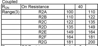
I bought 40 of them and picked 12. I remember that the picked ones varied as large as 20~30% from one another. But I did get each pair as close as single digit %.
By same batch I mean the same batch lettering A B C D E or F it's marked on the side, attached is the data from Silonex on what each letter means in resistance in the on state.
Attachments
Lightspeed remote control
Hi KK,
I have not bothered to assess the equivalent value of the pot due to lack of time. It would depend on the operating range you decided to use by selecting the values of the current programming resistors R1 to R4. I chose 39K for R1 to R4 to approximate the range suggested by Nelson Pass in his posts earlier in the thread. Have a look back there as he may have given this information. It it not critical in my system as all my source equipment is low impedance and the power mosfet driving my line array loudspeakers has a high impedance input.
You do not need the IR receiver to initialise the VCCS board for push button operation. The push buttons will control the dallas DS1802 as described in their application note.
Regards
Paul
Yes, a 1k caribration trimpot is only needed on the louder of the two channels, hand matching all the NSL32SR2S will get you close, then the trimpot calibration using 1k 1vpp sine wave and a dual trace ocilloscope will get the final matching down to +&- 1db if you don't have a scope then it is possible but difficult to use a good DMM.
Cheers George
Is it possible to use trimpots to match any NSL32SR2 together? they are quite expensive and id rather not buy 40+ to try match up if possible. also, whats the difference between the NSL32SR2 and the NSL32SR2S?
Thanks, Dan
Is it possible to use trimpots to match any NSL32SR2 together? they are quite expensive and id rather not buy 40+ to try match up if possible. also, whats the difference between the NSL32SR2 and the NSL32SR2S?
Thanks, Dan
You could try to use two volume controls, but people I know have been committed after a short time living with them, no seriously the trimpots are just there to do the final degree of matching after you've done the main matching of the 4 x NSL32SR2S, if you use the NSL32SR2 you will need double the amount to find 4 matched, it's worth paying the extra for the S "sorted" and try to get same batch letter as I explained a few posts ago this helps a lot.
Cheers George

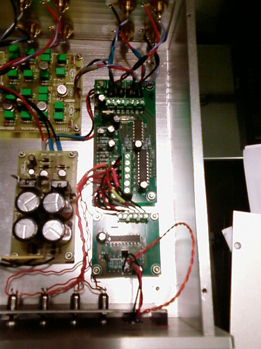
Thats a really sweet build! Congratulations
If I could make a suggestion my only one would be that you might sometime try removing the terminal blocks from the signal and running everything in the signal soldered.
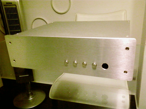
I love the enclosure!
Uriah
On closer inspection I cant really tell if the terminal blocks have anything to do with the signal.
So HOW do you like the sound?
If I could make a suggestion my only one would be that you might sometime try removing the terminal blocks from the signal and running everything in the signal soldered.
I love the enclosure!
Uriah
On closer inspection I cant really tell if the terminal blocks have anything to do with the signal.
So HOW do you like the sound?
Hi Uriad,
The signal side of the LDR are all soldered, blocks are for the LED part. Haven't got the chance to listen in my set up yet, but everyone who listen in the shop likes it. I think you have be receiving some orders from Singapore right?
My amp and DAC are still in the works.
Ps: The closure design was by me and made by the shop.
Hi Paul,
I still having a bit of problem with the button interface and the IRR unit. IRR can receive the signals but the VCCS only react to signals after 30sec from powering up. As for the switches, it works no problem without the IR board, but works only after VCCS is been control by the IRR or by powering up and cycle the power(10sec on, 5sec off and on again).
Are there voltages between common and the other (2 to 5) from a powered IR? Coz I reading some.
Cheers,
KK
Last edited:
Lightspeed Remote control
Hi KK,
Sorry you are having problems with the VCCS module. I have not had this problem with any that I have tested so far. Has anyone else had any similar problems?
Firstly check your wiring very carefully to see if there are any errors. Secondly is there any possibility that you have subjected the VCCS board to static discharge during assembly.
The IRR circuit floats above power ground on the same 5 volt ZR431 reference that supplies the DS1802. If you have assumed that the common terminal (terminal 1) on the six-way push button connector section that interfaces with the IRR board should be connected to ground this would upset operation.
Terminals 2 to 6 should all read 5 volts higher than terminal 1. When you actuate any switch connected to terminals 2 to 5 this terminal should go low to terminal 1 potential.
I hope this helps. If you feel that all wiring is correct and all measurements are correct the static discharge possibility is worth considering. If you are still struggling with this after the checks send the VCCS module back to me together with the IRR module and I will test everything and repair any faults for you free of charge.
Regards
Paul
Ps: The closure design was by me and made by the shop.
KK
Hi daredevil_kk,
What is the name of the shop? Next time I'm in S'pore maybe I can check it out.
Garrett
Paul,
I would like to re-use your remote control design, if I may, with some modifications. My 6 channel amp is connected full time to a PC and I have a USB to serial module that I can control the RS-232 lines via code on the PC, to drive SPI inputs to 3 cascaded digital potentiometers (probably the Microchip 42100 100K pot - its 1/3 of the price of the DS chip locally and has a 256 step range vs the DS chip 64). One advantage of PC control is that I can trim the the digital pots through software to compensate for any channel differences as I won't be able to get perfect matches across all 6 channels - I'll concentrate on L+R as matched, and RR+LR as matched, but will need to trim for centre, subwoofer, front and rear balance. I also will be using the SR3 LDR not the SR2, the SR3 distortion specs are better albeit they will be harder to match (I have a batch of 40 to pick from).
Basically I want to duplicate your 2 channel design for 6 channels however I have a couple of questions:
1) You have a current source driving the digital potentiometer (BSP129) and the opamp driving the LDR LED is also configured as a current source (output adjusting the current so that the voltage over the 39K sense resistor is the same as that over the DS1802 voltage divider). The opamp output current for the LED is sourced through the BSP129, so with 6 channels @ approx 15mA per channel worst case, the BSP129 runs out of steam as its rated to 50mA. It is also pretty difficult to find a JFET rated more than 50ma that would be appropriate to use as a supply current source, can you suggest an alternative? Can I get rid of the supply current source completely, as the opamps are regulating the current to the LED anyway?
2) What opamp and DS1802 version do you use? I assume any opamp with a single supply, output capable of rail-rail will suffice. Do you use the 10K, 50K or 100K DS chip?
3) You float the voltage across the DS1802 potentiometer, which is has a maximum potential of 5v as per the chip specs. Any reason for not using straight 5v supply for everything to remove the need for the zeners? I assume you can't get the current swing needed with the opamp with just 5v, as the LEDs have a voltage drop of 2.5v (+ the extra voltage drop for the opamp outputs which will not go quite rail-rail)?
4) Your sense resistors are 39K, which from a LTSPice model I knocked up has the LED being driven with a maximum of 500uA - a much smaller current than the LED is capable of. Is there a reason why you use this particular range? Is the resistance range more linear there, or is the distortion characteristics better?
5) What is the reason for the 1M resistor across the bottom of the DS1802 voltage divider?
I may have made a couple of wrong assumptions in the analysis above, so please put me on the right path - your input is appreciated!
- Home
- Source & Line
- Analog Line Level
- Lightspeed Attenuator a new passive preamp