Well I found a spare hour today.... and instead of concentrating on my new amp I thought I would bypass the input on my Lepai...why not....quick job I thougt...
Now bypassed and it has absolutely nothing there...pin drops....nothing!
This is very strange! I completely bypassed everything by running the RCA inputs through shielded wire to two of the pots ( giving me a balance control!) and then onto a set of Slimic caps (left over from a Charize mod)... then to a new pair of 20K input resistors to repace the 8K2's in there (must be because of some upstream series resistance on the old tone controls...
But when I power up there absolutely nothin...not a bean..the speakers are silent...not even a turn on thump?
I have completely bypassed the entire input section with no connections to the board what so ever... is there somethimng else I need to sever on the tracks other than the input channels?
There are no bad conections/solder joints as I have DMM'ed the lot and there is no logical reason for the lack of sound...what gives?
Lostcause said:I completely bypassed everything by running the RCA inputs through shielded wire to two of the pots ( giving me a balance control!).......
I wonder if that opamp etc. is required if you are using the balance control? Maybe it will work without the balance control.
Were you able to separate the "Boss" control from the balance control without disrupting the signal flow?
Fin said:
I wonder if that opamp etc. is required if you are using the balance control? Maybe it will work without the balance control.
Were you able to separate the "Boss" control from the balance control without disrupting the signal flow?
hey fin,
When I say balance control, I just mean that I use one channel of each dual pot.
I also completely removed them from the board and rotated them to be isolated.
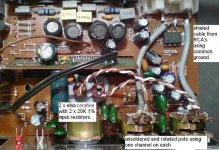
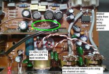
You can see from the pic that there is nothing untoward...wonder what happened? Pardon the Phone/camera quality...
Attachments
Fin said:Is it possible that something in the old "bypassed" circuit is still connected.....and somehow draining the signal away?
My thoughts exactly sir.... but where?
Is there something else connected on the power side that is upsetting the apple cart?
I don't know and it's too late for me to be bothered to be honest....time for bed
New day, new thoughts.....
What does the brown wire do in the twisted pair that hops off the balance contols to the caps?
I see that the white wire comes from the wiper - good. And the brown wire from ground - OK, but where does it go?
Where does the signal go after the cap and resistor? Right to the sub board? Did you break the traces from the sub board to the main PCB?
Put a finger tip on the connections of the new input caps. Got hum?
Hey Captain,
That brown wire is not connected at the other end, I just left the cat5 as a twisted pair and connect one end to ground to give it a semi shielded effect.... would have used the shielded wire but it got rather fiddly in there
The resistor is connected to the board where the other one was removed so it enters the signal path in exactly the same place but creates a break from the original traces.
No hum no nothing I'm afraid sir, even when you turn her on you don't even get the customary thump!... not even a click... but the power is definately there at the pins, I measured that as well.
It's really strange!
Hmmmm.... OK.
I have a modded Lepai that refuses to run on one of my SMPS - a 15V job. The LED lights, but no sound at all.
Go back to the standard 12V SMPS and all is good.
Don't know why it's that way. Bad contact at the power plug? Electric voodoo? Don't know. I put it on the shelf for the moment - might have to bring it back down.
I wonder if there is some kind of signal detection on the input that mutes it when there is nothing going through that elaborate input section? That's pretty much whats happening really, it seems like it is muted.
Now that I've completely bypassed the input it may be thinking there is no signal there?
Just a thought... I'll have a closer look at the mute pins later...
Now that I've completely bypassed the input it may be thinking there is no signal there?
Just a thought... I'll have a closer look at the mute pins later...
Did I say a lot of offset? No, it's the same but now there is no turn on mute circuit so I get a BIG thump with those 10uf Cerafines.
Not that I care at all...
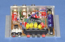
Before boxing her back up I put some copper shielding over the inputs and caps etc...
This is now the amp it should always have been
Excellent! as good as an amp6 once you have done all that I have
Now for my main amp to finish... come on Lee get a shuffle on
Not that I care at all...
Before boxing her back up I put some copper shielding over the inputs and caps etc...
This is now the amp it should always have been
Excellent! as good as an amp6 once you have done all that I have
Now for my main amp to finish... come on Lee get a shuffle on
Fin said:Great news & well done!
Can you give us more details about the mute circuit and exactly what you did to it?
Hi Fin, don't ask me to explain how the mute circuit works, it also appears to have an overvoltage aspect to it so that's probably why Pano's amp doesn't like 15V.
As far as removal is concerned you just need to remove the wire from the board to break the connection, it draws voltage on one of the wires and returns it to pin 11 on the other depending on the conditions.
I also removed the grounding resistor and the little inductor and just put a bridging wire in there to permanently connect it directly to ground. You leave them in I suppose and just remove the wire.
It really does sing now so I'm listening to it on my main system whilst I get my new amp finished. It's amazing how more 'open' the sound is with far better seperation and staging. I recommend shielding the inductors from the rest of the circuit, I think this also made a big difference, especially in such a small box.
Attachments
Good find on the mute circuit, Lee. I'll have a look at it.
Wanted to run the chip on 15V for a while to see how it does. Shouldn't be a problem, as the AMP6 runs on 14.5V all day without breaking a sweat. The diode at the input of the Lepai is going to drop the voltage a bit, so I may bypass it.
Wanted to run the chip on 15V for a while to see how it does. Shouldn't be a problem, as the AMP6 runs on 14.5V all day without breaking a sweat. The diode at the input of the Lepai is going to drop the voltage a bit, so I may bypass it.
panomaniac said:Wanted to run the chip on 15V for a while to see how it does. Shouldn't be a problem
Hi Michael, just wondering if you can do that without some extra diodes in there? Maybe that's why it has a protection circuit?
TA2020 datasheet..........
"Diodes (DO and DH) are Motorola MBRS130T3 (the DH diodes are required for VDD>13.5V)"
I changed out the diodes to the recommended ones when two of them failed after being left on for a couple of weeks.
About half way down the page there is a modded Lepai T-amp.......but the Google translation is not great.......
http://www.maurarte.com/T-AMP.htm
http://www.maurarte.com/T-AMP.htm
This small and amplifier economic (approximately 40 euro sent to house) mount chip Tripath TA2020 that fed to 14V leggermente distributes a advanced power to the TA2024 that equips the T-Amp. It widens is introduced with houses decorous but from the rather approximate finish. The printed circult is of rather low quality but fortunately the members are not in SMD. The scatolotto he has beyond the grip handle of the volume also that one of the bottoms (calls Boss to you!!) and that one of the acute ones. The switch who from the first moment seems a switch of ignition in reality puts in stand-by the member. The sound is not badly, to my warning better dell Amp-6 than 41HZ that it mounts the same one chip. The bottom is deep and fast, the scenica reconstruction is rather good, appreciable dynamics, but to my warning the medium range loses something in comparison with the T-AMP. Seen the good accessibility to the circuit the modifications in order to improve it have been innumerevoli. The objective was to improve the quality of the medium range and to render the behavior of the scatoletta still more dynamic. The Lepai mounts in income operational (a RC4558) a lot used in the effects for little indicated guitar but for applications Hi Fi. The first participation has involved the assembly of one hoof for IC and the istallazione of a NE5532 a sempreverde economic but from the good performance. The successive step has been the substitution of all the elettrolitici presents in series to marks them (8 from 3.3uF) with Wima.Successivamente polyester has eliminated is the diode valve anti polarity reversal that the inductance in series to the feeding and I have replaced the condenser of feeding from 2.200uF with a Elna low ESR. Not content I have replaced the two condensers from 100uF present in the immediate vicinities of the chip with others from 1000uF. The final touch has been that one to replace the inductances of the ricostruttore filter with wrapped others in air. To the end of all the job the quality of the small widens is improved very many above all in medium range where it is increased to the selettività and the precision of reproduction of the instruments. I have intentionally maintained the tone controls because to my warning the advantages that carry are by far advanced to the small imputable sonorous degradation to they.
Attachments
gychang said:what is the bottom line on this amp?, gather cheap, and with proper mod sounds good. Is this correct?
1. where does one buy the unit?
2. is there a picture of mod?, step by step, pano?
seems like the picture of the unit is hard to come by.
gychang
I modded mine to the point were most of the board became redundant
, to that end, its quite a big box for a small amp!There are quite a few pictures and diagrams of what to do further back in the thread but not one collectively.
I would recommend bypassing the entire input section and wiring it in (in-air) through new resistors and caps, replace the power caps and use either a new quality pot or one for each channel.
IF you can find one for the right price that is... an amp6 is better and cheaper in the long run otherwise......
- Status
- This old topic is closed. If you want to reopen this topic, contact a moderator using the "Report Post" button.
- Home
- Amplifiers
- Class D
- Lepai T-Amp with TA2020