HahahahaWhich valve audio circuits need accuracy?

Good one!
I think I got my answer to some degree.
Don't use LED's it in power stages, use them in pre stages.
right?
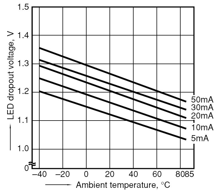
LED forward voltage is temperature dependent .
All junctions are. Be careful interpreting that graph- it's only valid at very low current, where bias LEDs are not run.
Which valve audio circuits need accuracy?
I thought bias accuracy is important for operating point and a shift may cause distortion ?
If you seek simple answers, then some people will give you simple answers. Better to understand the issues, then find your own answer to your own particular question.KenTajalli said:Don't use LED's it in power stages, use them in pre stages.
right?
"Accuracy" is not an absolute term. When good valve samples vary by maybe 20% in current and hence bias voltage, and vary by more than that over their useful life, there is little point in looking for much more than that in bias accuracy. Instead, design circuits which can cope with reasonable shifts in bias.nec3 said:I thought bias accuracy is important for operating point and a shift may cause distortion ?
People who design by simulation may choose a 'sweet spot' where distortion reduces and may then believe that they have to maintain this; real life is not like that. The 'sweet spot' might not exist, or may move around, and even at it the distortion will be quite different from the simulation results.
You graph shows the LED voltage changing by about 50mV between 20 and 50 degrees. That's a negligible change for valve bias. Worry about volts, not millivolts.I thought bias accuracy is important for operating point and a shift may cause distortion ?
I must admit, I am new to LED biasing, and did learn alot from here and other articles.If you seek simple answers, then some people will give you simple answers. Better to understand the issues, then find your own answer to your own particular question.
My assumption was (because I had seen the red-light article) that it was a usual thing to bias output stages with LED's - hence my question!
My assumption seems wrong now, each one has it's own uses.
So it seems the first reply was more on the ball that I had understood.
So thanx M Gregg.
You graph shows the LED voltage changing by about 50mV between 20 and 50 degrees. That's a negligible change for valve bias. Worry about volts, not millivolts.
I agree.
SY used 7 LEDs in serial which makes 7*50 = 0.35 V. which also looks not so high.
Ok. I withdraw my words.
It's actually even smaller than that since the variation in Vf with temperature should be considerably less at a full-on running current rather than the very low currents in that graph.
The tolerance (Vfmin and Vfmax) maybe a problem rather than temp. variation ?
It is around 1 volt between min and max. If use different "bin" LEDs, according to data sheet, it is possible to have a 7v variation. Then, checking LED voltage before manufacture may be needed. Again, not so big problem as long as kept under control.
http://www.vishay.com/docs/83171/tlur640.pdf
I must be missing something. Doesn't that graph show operating currents from 5 to 50mA? That's not exactly low for an LED. And I believe the tempco of diodes is substantially independent of current anyway?It's actually even smaller than that since the variation in Vf with temperature should be considerably less at a full-on running current rather than the very low currents in that graph.
In addition to what others have said, you don't see that wide of a temperature swing in actual operation. You are looking at a graph of operating conditions over the entire temperature range for the LED.
what is the temperature swing over a year period where the amp will be operated?
In my house it is less than 5C.
If you are designing guitar amps to be used outside, the swing would be greater.
what is the temperature swing over a year period where the amp will be operated?
In my house it is less than 5C.
If you are designing guitar amps to be used outside, the swing would be greater.
I must be missing something. Doesn't that graph show operating currents from 5 to 50mA? That's not exactly low for an LED. And I believe the tempco of diodes is substantially independent of current anyway?
The y-axis is labeled "dropout voltage" so that would imply low current. But yes, the curves show currents. So without any context, that's a pretty ambiguous graph.
Inside the actual enclosure, temperature might vary a lot more than just 5C. Specially if tubes and/or regulated PSU's are involved to warm things up a bit.
For some reason, I'm not seeing a lot of issues with bias drift in the tubed phono stages, line amps, and power amps in my system.
For some reason, I'm not seeing a lot of issues with bias drift in the tubed phono stages, line amps, and power amps in my system.
haha me neither, but it does warm up nice in there
You can view this as a good thing, since the elevated interior temperature (once warmed up) serves as a kind of buffer against changes in outside temperature. As long as you tweak your circuit at full running temperature it should then stay nicely stableInside the actual enclosure, temperature might vary a lot more than just 5C. Specially if tubes and/or regulated PSU's are involved to warm things up a bit.
- Status
- This old topic is closed. If you want to reopen this topic, contact a moderator using the "Report Post" button.
- Home
- Amplifiers
- Tubes / Valves
- LED or fixed biasing?