A possible LED-less equivalent?
(PER SY: doesn't fly)
GoatGuy
See post 14. No blocking distortion.
(PER SY: doesn't fly)
GoatGuy
Attachments
Last edited:
Does grid-bias suffer from blocking distortion, or poor recovery from overload?
Yes- the source there is the RC time constant of the coupling cap and the grid bias resistor.
Had a quick look. This is single-ended design, with only local-feedback (i guess that's why no bypass caps were used), not a very common occurrence.Look at post #12 here: http://www.diyaudio.com/forums/tubes-valves/259333-6b4g-ecc83-2.html#post4256787
No cathode by-pass, not even on finals. No coupling capacitors. No transformer coupling except to speakers, only film caps... but it is not push-pull.
Ian
I am with you, that capacitors are better avoided, and I wish I could do without bias also.
Both are necessary evils, so better used as little as possible.
On many designs, an input stage without a bypass cap, bass response may suffer.
Take a look at this:Yes- the source there is the RC time constant of the coupling cap and the grid bias resistor.
http://www.computer-surgery.net/ebay/new_edison.pdf
Similar to your red-light design, but with grid-bias.
I never measured (or heard) any of those distortions on this.
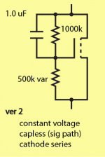
Version 2
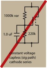
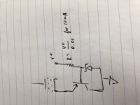
Sy, if I'm correct, this subtle rearrangement serves to act as a constant voltage source, instead of a constant current one. The trick is that the capacitor actually does pass the audio, as it varies … modulating the Zeff of the MOSFET. Hmmm… I don't think I've seen this circuit before.
GoatGuy
(PS: as "constant" perhaps as a forward biased diode!)
Attachments
Similar to your red-light design, but with grid-bias.
I never measured (or heard) any of those distortions on this.
Clip it and watch what happens.

Noting that Bappe's definitions of bias are the classic English language usages expressed more clearly, and consistent with my understanding from countless old college textbooks and other sources.
I use fixed bias in output stages, I'm not a fan of 60 or more leds in series parallel even though it can be done. Blocking distortion can be managed or eliminated with power drive, CF or IT coupling with a low source impedance bias supply.. (You can also select RC coupling time constants that reduce the effect as well within reason although going too far may result in premature LF roll-off.)
Battery bias or LED bias in low to moderate level stages at my whim.. Cree diodes of various sorts as well as 1N4148 or 1N4150 in small signal apps like phono stages. My line stages all use fixed bias.. CCS are known to show up outside of the signal path and sometimes in it..
No fan of cathode bias although admittedly it solves a lot of problems with tube parametric behavior..
Not really. The LED strings still need a small resistor each to ensure reasonable current sharing. The total combination is not much lower in impedance than a few thousand microfarads of bypass cap.LED biasing provides very low dynamic resistance in the cathode circuit of a tube output stage.
No, at least not in English. Fixed bias means applying a 'fixed' (may be adjustable) bias voltage to the grid, other than simply grounding it. Cathode bias (aka self bias or auto bias) means using a resistor in the cathode circuit to generate the bias voltage. Grid bias is a vague term which basically just means 'biasing', by whatever means .What you are actually referring to is "Grid bias". Grid bias is when you adjust a negative supply with a trimmer to reference the signal input. "Fixed bias" requires the cathode to be elevated with a (hefty) resistor, while the grid is referenced to ground.
LED bias is not 'mainly' used on any power valves! I've only seen it done once, and that was SY's Red Light Disctrict, which used EL84s.I understand LED biasing is mainly used on tubes such as EL84,
A transformer alone will cost way more than a bag of LEDs... But OK, you don't usually need a separate transformer for fixed bias.A separate low power transformer, few resistors and pots etc. will not cost much more than tens of LED's wired together
This is only half true. There are two capacitors involved with blocking: the coupling cap and the cathode bypass cap. LED bias only eliminates one of these. The coupling cap can easily be the greater contributor, depending on their relative time constants. LED bias is no more or less resistant to blocking than fixed bias.LED-biased stages don't have blocking distortion.
Last edited:
On scope nothing happens, it just clips.Clip it and watch what happens.
On listening, driving a pair of "Sonus Faber Concerto home" rated 6 Ohm connected to the 8 Ohm taps (that's all I have) sounds very clean, upto where it runs out of juice, which is more than you expect from such a combination.
Question is:
What am I looking for?
You're looking for crossover distortion during the first hundred milliseconds (or more, depending on time constant) after clipping. Here's as good an explanation of it as I've seen:
http://www.aikenamps.com/images/Documents/Crowhurst_blocking.pdf
http://www.aikenamps.com/images/Documents/Crowhurst_blocking.pdf
That constant-voltage drop circuit, revisited
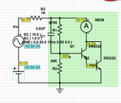
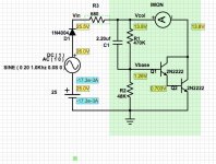
SY, I wasn't satisfied with leaving the "simulated LED circuit" alone; I used PartSim to do a PSpice sim, which … naturally … took far more time than I anticipated.
However, my intuition about the circuit is correct. Excusing for the moment that the transistor part numbers in the attached circuit aren't optimal, I found 3 things:
1. The use of a capacitor between base and collector markedly stabilizes circuit
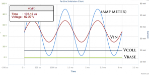
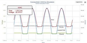
2. The voltage in darlington configuration at Vcoll varies by only millivolts over current ranges of 12 ma to 55 ma.
3. The voltage-drop is easily "programmable" via adjusting the base-to-emitter shunt resistor. (smaller resistor → higher collector regulation voltage).
Who knows… maybe this, or the MOSFET version, might become the "next big thing", since strings-of-LEDs aren't exactly adjustable after they're all soldered together! Its also potentially quite inexpensive to build.
GoatGuy
PS: My use of a DC supply + an AC sine supply, plus the 1K resistor was an absurd but effective hack in order to produce a simulation of the cathode-current of a tube being run in Class A mode. I'm sure there might be a more elegant way, but this for now was it. Please accept apologies.
In use, the two supplies and the resistor would be eliminated, and the circuit would be inserted between cathode and ground.
… bunch of stuff …
SY, I wasn't satisfied with leaving the "simulated LED circuit" alone; I used PartSim to do a PSpice sim, which … naturally … took far more time than I anticipated.
However, my intuition about the circuit is correct. Excusing for the moment that the transistor part numbers in the attached circuit aren't optimal, I found 3 things:
1. The use of a capacitor between base and collector markedly stabilizes circuit
2. The voltage in darlington configuration at Vcoll varies by only millivolts over current ranges of 12 ma to 55 ma.
3. The voltage-drop is easily "programmable" via adjusting the base-to-emitter shunt resistor. (smaller resistor → higher collector regulation voltage).
Who knows… maybe this, or the MOSFET version, might become the "next big thing", since strings-of-LEDs aren't exactly adjustable after they're all soldered together! Its also potentially quite inexpensive to build.
GoatGuy
PS: My use of a DC supply + an AC sine supply, plus the 1K resistor was an absurd but effective hack in order to produce a simulation of the cathode-current of a tube being run in Class A mode. I'm sure there might be a more elegant way, but this for now was it. Please accept apologies.
In use, the two supplies and the resistor would be eliminated, and the circuit would be inserted between cathode and ground.
Attachments
Last edited:
At the cost of a low power supply (or stealing a few ma from the B+), you could do it pretty easily with a bipolar or a darlington. I show a Zener here, but it could be series LEDs (single string) or whatever. The question on all these circuits is recovery time after overload- the LEDs snap back essentially instantaneously.
Attachments
At the cost of a low power supply (or stealing a few ma from the B+), you could do it pretty easily with a bipolar or a darlington. I show a Zener here, but it could be series LEDs (single string) or whatever. The question on all these circuits is recovery time after overload- the LEDs snap back essentially instantaneously.
Cool… using a PNP as an "upside down" emitter follower. That ought to work pretty darn well. You only need 1 ma or so feeding the Zener in order to realize potentially up to ½HFE milliamps of cathode drive.
PNPs though tend (all things being equal) to be on the slow side. I still would expect recovery in under 1 μS. As you say, the deployment of a Darlington cuts even further then B+ supply drain. To dozens of microamps. One could insert a trimming potentiometer in series with the zener (on the ground side), plus a capacitor across it (not in signal path!) to make a variable zener in a small range. The cap would be there to squash both purported and actual trimpot noise, long term
Last edited:
The cap is what would worry me for overload recovery. But hey, you're the guy with the sim software, tell me!
edit: Sorry for the neck cramp.
Neck Cramp ≡ LOL
The cap doesn't affect recovery 'cuz its on the "base" side of the emitter follower, and serves just as a low pass filter for the variable voltage drop potentiometer.
BTW: the combination I put up there that didn't include a Zener gets near-absolute (zener-like) regulation because of the near-constant VBE voltage drop. Kind of like a LED of low forward voltage. In the end, the constant-voltage is straight forward: Vreg = (R1+R2)/R2 × VBE of the darlington pair (1.26V in diagram).
If I leave the R1 (470k) alone and put a 15K "safety" resistor in series with a 25K Allen Bradley trimpot, one can vary the voltage from (15k + 0k) = 40.7 V down to (15k + 25k) = 16.4 V. A plenty broad range for output tubes of ordinary garden variety.
I've included a followup with the Class-B mode push-pull behavior. It demonstrates saturation/cutoff recovery. I used 1 μS sim steps… to catch the glitches.
GoatGuy
Attachments
Regarding linearity, did you once say that red LEDs had a dynamic impedance of 0.4Ω? Say I had 8 of them for 3.2Ω and an output stage that swings 10Ma with a wanted 70uVg-k noise floor, and these dropped 32mV. How significant would their non-linear contribution be?Besides simplicity (even the array I made for my power amp was simple and cheap), low noise, and stable voltage,http://syclotron.com/?p=129
Not quite that low! Depending on the LED, more like 2-4R, with the HLMP6000 that I use being on the low end of that range. The 10mA swing implies that your actual idle current is higher? Be careful about exceeding the ratings! You can work this to your advantage- paralleling strings can drop the non-linearity (assuming it's significant in the first place!), and the closer the stage gets to a horizontal load line, the less the nonlinearity matters. And low mu also reduces the effect of any nonlinearity.
Re: noise, a good red LED will show something like 0.4nV/rt Hz voltage noise density. In series, the noise adds as power, that is, 8 in series will give 0.4nV/rt Hz * sqrt8 = 1.1 nV/rt Hz.
Re: noise, a good red LED will show something like 0.4nV/rt Hz voltage noise density. In series, the noise adds as power, that is, 8 in series will give 0.4nV/rt Hz * sqrt8 = 1.1 nV/rt Hz.
- Status
- This old topic is closed. If you want to reopen this topic, contact a moderator using the "Report Post" button.
- Home
- Amplifiers
- Tubes / Valves
- LED or fixed biasing?