Oops, I said that wrong. The +2.5Vdc is the collector of Q10. I thought the jumper across the output to either side of R36 was because the outputs were not in the circuit. I will go ahead and remove them and do the jumper. Maybe the voltages on Q10 & Q11 are not important since I have D7 & D8 opened. I will reconnect them. Once I have everything setup I will hook up the scope and go from there.
Thanks
Thanks
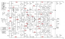
leach superamp
They may not have moved the speaker out but you many of heard a small thud at power up... still back to the task in hand solving this amp back to working order.. speaker protection circuit is a must with large amps.")
I just tested all of my other amps, and not one moved the woofers on my speakers. I really think I was seeing some serious offset when this thing was starting up. It reminded me of a few years ago when I bought a Soundcraftsmen amp and just plugged it in with the speakers attached. I heard a similar sound and the speakers flexed. I shut it down and checked and had rail voltage on both sides. I considered myself very lucky that I didn't ruin the speakers. I never did that again. From that point forward, I always check for offset on the outputs before I hook up any speakers. The problem with this Superamp is it measured really good when up and running. It only did that for about 2 seconds and then stopped. You can be sure I will not hook any speakers up to this again until I'm sure that won't happen again. Also, I have about 6 guitar and bass amps so I checked them too. None of them moved the speakers that way this did.
The journey continues.......
They may not have moved the speaker out but you many of heard a small thud at power up... still back to the task in hand solving this amp back to working order.. speaker protection circuit is a must with large amps.
No comparison. with the Superamp the cone would come full flex forward and the hum was loud. I'm sure that it was too high a voltage. I need to really get everything right this time. If it's questionable at all I'm not going to use it. I have plenty of amps. I don't need to be harming my speakers. I've been car shopping all day so haven't been able to tear into it. I will maybe get to it this evening.
Blessings, Terry
Blessings, Terry
Well I thought I was getting there. I replaced Q14 and there was no change. Then I replaced Q16 and Q26. I brought it up on the variac and was able to get it up to 90Vdc rails without it swinging negative. I had only about -1.4V offset so I decided to take some measurements so we could get it the rest of the way. I had just finished filling out the schematic when I realized that I missed the base of Q16. So I went back out and powered it up again to get that reading. What do you know, it swung negative again. I did notice that the rails have gone up to 91.5V. So I just tried it, and if I bring it up slowly on the variac, I get to about 87V rails with about 1.4V offset. As soon as it hits 88VDC rails it swings to -33Vdc offset.
So, do you guys have any idea what could be causing it to do that?
I'm attaching the readings I got just before it swung negative.
Thanks, Terry
So, do you guys have any idea what could be causing it to do that?
I'm attaching the readings I got just before it swung negative.
Thanks, Terry
Attachments
What's the voltage at the junction of R3 and R5, and what happens if you hard ground it? That offset has got to be coming from somewhere. It's consistent with either a lot of input bias current or something floating that shouldn't.
The input was shorted for this so without measuring it I would say 0.00. My biggest concern is the way it suddenly goes negative when it reaches a certain rail. Tomorrow I will hook up the scope and see if I can see any oscillation.
Thanks
With those readingand input shorted, the diff pairs have to be really out of balance - either Q1 is on much harder than Q2, or Q3 is on much harder than Q4. One of the quad may be open - perhaps the voltages across the degeneration resistors will offer a clue. If one side is on hard you should be able to tell which.
Also, not likely but possible - you don't have one of the input transistors in backwards, do you? Reverse hfe is extremely low, which can result in very high input bias currents. And if it goes into avalanche it will REALLY upset the differential balance. And no, it won't blow up - just act really weird.
Also, not likely but possible - you don't have one of the input transistors in backwards, do you? Reverse hfe is extremely low, which can result in very high input bias currents. And if it goes into avalanche it will REALLY upset the differential balance. And no, it won't blow up - just act really weird.
Sorry, here I go again showing my ignorance. Not sure why I can't get my head wrapped around these terms. Which resistors are you speaking of when you say "degeneration resistors"?
I will double check Q1-Q4 again, but three days ago, this channel had .007mv offset. I suppose it is possible that one of them were damaged when I shorted the output. I have a lot those resistors and can easily change them out. Let me take some readings around those with the huge offset and see what I can find. I'll get back to you soon.
Thanks, Terry
Terry, are there any troubleshooting jumpers/resistors installed for the latest round of measurements? Is there a load resistor?
If you are using 0R47 for R47 etc, and you are showing -1.42V DC offset, then Q20 is passing ~120 mA : (1.41-1.35)/.047. But that doesn't match the -1.38V at Q21's emitter. It's hard to imagine how Q21's emitter could be more positive than the output.
Are D7 and D8 back in the circuit? Either way, something is off that the Collectors of Q10 and Q11 are significantly closer to the rails than their bases. For example, if the diodes are in circuit and Q10 is conducting it's collector should be D7's Vf below D7's anode or .281V. There is no connection to pull it more positive. The Vbe shown for Q10 and Q11 are not enough to turn them on. Are you sure that 3.22 and -4.50 voltages are measured/marked at the correct location?
To further clarify, degeneration resistors are R7,8,9,10
Well I thought I was getting there. I replaced Q14 and there was no change. Then I replaced Q16 and Q26. I brought it up on the variac and was able to get it up to 90Vdc rails without it swinging negative. I had only about -1.4V offset so I decided to take some measurements so we could get it the rest of the way. I had just finished filling out the schematic when I realized that I missed the base of Q16. So I went back out and powered it up again to get that reading. What do you know, it swung negative again. I did notice that the rails have gone up to 91.5V. So I just tried it, and if I bring it up slowly on the variac, I get to about 87V rails with about 1.4V offset. As soon as it hits 88VDC rails it swings to -33Vdc offset.
So, do you guys have any idea what could be causing it to do that?
I'm attaching the readings I got just before it swung negative.
Thanks, Terry
Hi Terry-
Have you measured the voltage on the collectors of Q18-21 while you bring up the rails?
I believe R7-10 are 330R and the differential input current should be 2.5 mA per leg, so the voltage across them should be roughly .825V.
Do measure the voltage at the junction of R2, R3 and R5. This will help determine if Q1 and Q3 base currents are within normal limits. Current should be ~tens of microamps, so across 1K2 you should see a few tens of mV.
I guess that's enough measurement points for a while.
Do measure the voltage at the junction of R2, R3 and R5. This will help determine if Q1 and Q3 base currents are within normal limits. Current should be ~tens of microamps, so across 1K2 you should see a few tens of mV.
I guess that's enough measurement points for a while.
Note: The measurement on the above chart were taken before the "avalanche" set back in.Terry, are there any troubleshooting jumpers/resistors installed for the latest round of measurements? Is there a load resistor?
No, I removed all jumpers and replaced diodes. Nothing on the output.
If you are using 0R47 for R47 etc, and you are showing -1.42V DC offset, then Q20 is passing ~120 mA : (1.41-1.35)/.047. But that doesn't match the -1.38V at Q21's emitter. It's hard to imagine how Q21's emitter could be more positive than the output.
I am using .33R resistors for R45-R48 if that matters.
Are D7 and D8 back in the circuit? Either way, something is off that the Collectors of Q10 and Q11 are significantly closer to the rails than their bases. For example, if the diodes are in circuit and Q10 is conducting it's collector should be D7's Vf below D7's anode or .281V. There is no connection to pull it more positive. The Vbe shown for Q10 and Q11 are not enough to turn them on. Are you sure that 3.22 and -4.50 voltages are measured/marked at the correct location?
Yes, D7 & D8 are back in.
To further clarify, degeneration resistors are R7,8,9,10
Here are some readings I got this morning with a quick test.
With the rails set at 85V
Q1E= -.594
Q2E= -1.318
Q3E= +.537
Q4E= -.203
R3-R5J= -22MV
R7-R8J= -1.426
R9-R10J= +.664
With rails set to 90V
Q1E= -6.62V
Q2E= -7.79V
Q3E= -14.28
Q4E= -17.48
R3-R5J= -6.00V
R7-R8J= -7.58
R9-R10J= -15.14
Hi Terry-
Have you measured the voltage on the collectors of Q18-21 while you bring up the rails?
I will check those.
Thanks
Why didn't just replace them earlier?
I just replaced Q1-Q6. Now everything is beautiful. Offset is about 33mv. Everything checks side to side. I had no idea the front end had such a huge affect on everything. Thanks to all of you for sticking with me through this. I sure hope someone else can learn from my mistakes. Once I get everything put back together I'll give a report on how it sounds.
Are there any readings you guys would like to see while I still have it all out of the case and accessible?
Thanks again!
Blessings, Terry
Check the Vdrops of the 4 degenerations resistors. This will tell you the imbalance in the currents passing through the 4 input transistors.
Check the Vdrops of the Vas degen.
Check the Vdrops of the base stoppers.
Check the change in output bias current (Vdrop of the emitter resistors) as the amp warms up from cold to fully warmed up.
Artifically heat up the sink to raise the output temperature to mimic extreme weather heating. And check the output bias at this artifically high temperature.
While doing all this repeatedly recheck the output offset.
Connect your source and recheck your output offset. Switch off your connected source and check the output offset.
When you are happy that it passes all these tests, then connect a cheap disposable speaker and listen for a bit.
Finally build and fit a speaker delay circuit that also detects excessive output offset and triggers that output switch. Now you can fairly safely attach your expensive speakers.
The front end probably got severely overloaded while troubleshooting. When an amp heads for the rail, it can break down (zener) the input transistors. 85 volts at the inverting input, zero at the noninverting = not good. It doesn't always kill the input devices but it can. Op amps often use protection diodes between the inputs to keep that from happening. A pair of 1N4148's in inverse parallel (or four in series parallel) would do the trick.
For next time. Leave it alone now that you've got it working.
For next time. Leave it alone now that you've got it working.
Congratulations Terry. Andrew gives sound advice for ensuring long term reliability since many of your parts have been stressed.
If you need a speaker delay/protection circuit I can send you the one used in the Hafler DH-500. It fits the requirements Andrew sets out and is designed to run off of ~90V rails.
If you need a speaker delay/protection circuit I can send you the one used in the Hafler DH-500. It fits the requirements Andrew sets out and is designed to run off of ~90V rails.
Check the Vdrops of the 4 degenerations resistors. This will tell you the imbalance in the currents passing through the 4 input transistors.
Check the Vdrops of the Vas degen.
Check the Vdrops of the base stoppers.
Check the change in output bias current (Vdrop of the emitter resistors) as the amp warms up from cold to fully warmed up.
Artifically heat up the sink to raise the output temperature to mimic extreme weather heating. And check the output bias at this artifically high temperature.
While doing all this repeatedly recheck the output offset.
Connect your source and recheck your output offset. Switch off your connected source and check the output offset.
When you are happy that it passes all these tests, then connect a cheap disposable speaker and listen for a bit.
Finally build and fit a speaker delay circuit that also detects excessive output offset and triggers that output switch. Now you can fairly safely attach your expensive speakers.
Hi Andrew,
I would love to check all of that. Would yo be so kind as to look at the circuit and give me the resistor numbers for the Vas degen, and base stoppers?
Thanks
Hi Bob,
I used to own a P500 Hafler. I have the manual in pdf somewhere. I would like to have the circuit for the speaker protects if you wouldn't mind. I guess I had better put one in this amp.
Thanks again.
Last edited:
- Status
- This old topic is closed. If you want to reopen this topic, contact a moderator using the "Report Post" button.
- Home
- Amplifiers
- Solid State
- Leach Superamp, round 2