OK, so I went on a quest this morning and Googled Leach Superamp images. Out of maybe a hundred or so pics of amps I saw one of two that had some twisted wires in them and from what I could see, there were less than what I have done.
Please show pics of the amps you guys have built so I can see which wires you think need to be twisted together.
Thanks, Terry
Please show pics of the amps you guys have built so I can see which wires you think need to be twisted together.
Thanks, Terry
Try this exercise. Trace the current flow from the secondary tx winding to the rectifier. Do this for one half of the supply (eg negative OR positive rail.). Trace as far as the smoothing cap. Imagine the cap charging / discharging. Ignore any circuitry after the cap.
You should end up with a loop. The area inside that loop needs to be minimized hence twisted pairs.
You should end up with a loop. The area inside that loop needs to be minimized hence twisted pairs.
Try this exercise. Trace the current flow from the secondary tx winding to the rectifier. Do this for one half of the supply (eg negative OR positive rail.). Trace as far as the smoothing cap. Imagine the cap charging / discharging. Ignore any circuitry after the cap.
You should end up with a loop. The area inside that loop needs to be minimized hence twisted pairs.
OK this is what I have on my transformer. The secondary has 4 wires. two of those are attached together to form the center tap and go to the star ground. the other two go to each side of the bridge. The bridge is approximately 3" from the cap. From the bridge, the positive wire goes to the + terminal on the one cap and the negative wire goes to the - terminal on the other cap. These wires are 3" long. Presently, I have the two wires going to the center tap twisted together and the two wires coming from the secondary going to the bridge are twisted together. The wires going from the bridge to the caps are very short and heading two different directions so the only way to twist those would be to make them longer. Easily accomplished if necessary. Please tell me what I'm missing.
Thanks
With the board's rail connections at opposite sides, it seems counterintuitive to twist the power leads, especially with such short runs. With my Leach 4.2s I had a little hum until I twisted the leads, ran them from the PSU caps, straight down to the chassis along the base and underneath the amp boards to the center then split them to the board connections.
Looking for good examples of cable routing in DIY amps can be an exercise in futility. Try some of the commercial amp repair threads.
Looking for good examples of cable routing in DIY amps can be an exercise in futility. Try some of the commercial amp repair threads.
Exactly! I think that's simply because the diagrams showing how to build the projects usually stop at the edge of the PCB or the connectors. The part where you need to connect things up is either assumed, shown as a connection reference like A-a, B-b etc. or a sketch such as you see with old Hafler/Dynaco kits.....Looking for good examples of cable routing in DIY amps can be an exercise in futility......
We have moved on since rat's nest wiring or looms were used to connect the internals of electronic equipment and you need to read a textbook, a DIY handbook or get yourself work as a pro. technician even to learn the part that takes something from working to something working well - noise and distortion wise, at least.
If it wasn't obvious from the threads, discussion and topics in Bob Cordell and Douglas Self's books being promoted, then buying either those or the late Randy Slone's books on amplifier construction will save a lot more wasted time and money spent on kits and parts in the search for audio nirvana. Wiring and grounding are significant parts of build quality for technical reasons, though some folks seem fixated on the neatness and architectural order inside the box too. Good for them, if it meets the real requirements too.
Learn a little - get this one done right before looking for something better
")
OK this is what I have on my transformer. The secondary has 4 wires. two of those are attached together to form the center tap and go to the star ground. the other two go to each side of the bridge. The bridge is approximately 3" from the cap. From the bridge, the positive wire goes to the + terminal on the one cap and the negative wire goes to the - terminal on the other cap. These wires are 3" long. Presently, I have the two wires going to the center tap twisted together and the two wires coming from the secondary going to the bridge are twisted together. The wires going from the bridge to the caps are very short and heading two different directions so the only way to twist those would be to make them longer. Easily accomplished if necessary. Please tell me what I'm missing.
Thanks
If I understand this correctly you have twisted the two center tap wires together as one pair and the remaining two wires as the other pair. This is the incorrect way of doing it. You should have the + wire twisted with one of the centre tap wires and the -wire with the other centre tap wire.
You should also have more than one star ground. At least one for the main signal grounds and one for the PSU grounds. Having light and heavy current sharing a single star ground point is not good.
One last thing (I have recently changed my mind about) its not all about having the shortest length wires as possible. Loop area is just as important.
@Bob Ellis
Perhaps I'm recalling older products too. Here, in the 1970's, we referred to a lot of Dynaco kits and other products, papers etc as Hafler-Dynaco. That's before Mosfets proliferated, by which time all DIY kits here showed the appropriate twist and routing routine for rail and AC leads.
Memory is not that good for the specific details of that earlier stuff but I did build or assist on some Dynaco transistor kits which were relatively popular here too. I do recall pre-cut leads being supplied but nothing about twisting rail or AC leads, though.
Professor Leach returned signal and power grounds separately on his board. The pair of connections makes it a star of stars even if just using a single external star. So, do we twist the two ground returns together with the power leads?
I would say not. Just thinking about flow and return paths. Would it be best routed well away from the heavy currents in the PSU lines?
This is a direct quote from Dr Leach's construction docs.
The only way I diverted from that was that I used a 1/4-20 bolt that attaches to the bottom of the case, runs up between the two caps to a bar that attaches the - terminal of one cap and the + terminal of the other. The top of that bolt is being used as the central ground. The only wire that is not attached per the instructions in the earth ground from the AC which is landed on one on the heatsinks near the AC plug.
The central ground point can be made with a #4 or #6 machine screw through the bottom panel with several #4 or #6 solder lugs and a nut over it inside the box. The solder lugs must make good electrical contact to the bottom panel. Do not use Radio Shack solder lugs.
The following wires connect to the central ground point: the green wire on the AC line cord, the ground wires for the filter caps, the transformer center tap, two ground wires from each circuit board, and the two loudspeaker ground wires.
The only way I diverted from that was that I used a 1/4-20 bolt that attaches to the bottom of the case, runs up between the two caps to a bar that attaches the - terminal of one cap and the + terminal of the other. The top of that bolt is being used as the central ground. The only wire that is not attached per the instructions in the earth ground from the AC which is landed on one on the heatsinks near the AC plug.
I understand what you are saying, but if you picture the circuit that forms the secondary of my transformer the flow of current flows from the - terminal at the bridge through one set of windings, up to the center tap, then back down into second set of windings and up to the + terminal on the bridge. So with that picture in mind It would seem that the two wires going to the center tap are indeed send and return. Besides, the wires going to the center tap are going to a different location than the ones going to the bridge.If I understand this correctly you have twisted the two center tap wires together as one pair and the remaining two wires as the other pair. This is the incorrect way of doing it. You should have the + wire twisted with one of the centre tap wires and the -wire with the other centre tap wire.
Last edited:
Your right, I don't have any hum. I have been looking through a lot of pics of commercial amps and see very few twisted wires. Most are just run nice and cleanly along straight paths and zip-tied together. I actually twisted all of mine except the grounds. I thought about redoing the ground wires to tidy it up but that would have required replacing a few and as they are they all reach fine.
Truth is, the amp served it's purpose. I learned a lot and finally got it playing. It's not like I need it. I have lots of amps to listen to. If I ever get around to building those electronic crossovers, it may end up in a Bi or Tri-amp setup.
Thanks to everyone for all the kind help.
Blessings, Terry
Truth is, the amp served it's purpose. I learned a lot and finally got it playing. It's not like I need it. I have lots of amps to listen to.
If I ever get around to building those electronic crossovers, it may end up in a Bi or Tri-amp setup.Thanks to everyone for all the kind help.
Blessings, Terry
leach superamp
Just a hair under 7 spaces. It is 12" tall, 7 spaces is 12.25". Close enough for me.
Here it is in the A/B amp stack in the room. On top is the Low TIM, then the Superamp, then the Symasym and on the bottom my first DIY build, the Eliot P101 three channel.

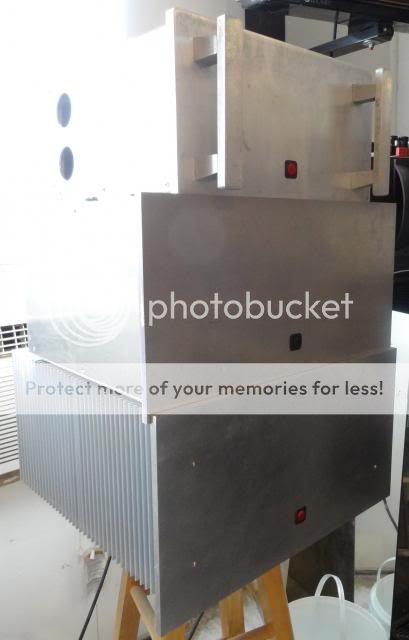
Here is a pic of the room heaters. Top is a TO3 based Krell KSA50, middle is a KSA50 with 6 pair of Plastic outputs per side. On the bottom is my Aleph-X. Soon to be something else since it sounds lousy. I may turn it into a KSA100 that I have boards for.
your need a strong rack case with wheel's for them heavy weight amps...


oh crap and after the epic battle you had with things only to be back to square one again, still you've hopefully got a good side to check things out.. start via ordering some new o/ps and drivers etc.. this amp has short circuit protection built in but only limits the base drive to the o/p's and might not save them if the short is left in place... spk protector's act when dc is found at o/p thus saving your spk's being cooked..
Just hope you get things back on track again..time to warm up the soldering iron it's going to be a loooooooooooong night and coffee pot at the ready...
Just hope you get things back on track again..time to warm up the soldering iron it's going to be a loooooooooooong night and coffee pot at the ready...
leach superamp
Look in to adding shut down circuit that will trigger and kill power to the whole unit in case this happens again..
Shorted the output today on one side and now have 82Vdc on the output. Fortunately I did while there was not speaker attached. Maybe I had better start installing speaker protection in my amps to make them more idiot proof since I seem to be one lately.
Look in to adding shut down circuit that will trigger and kill power to the whole unit in case this happens again..
- Status
- This old topic is closed. If you want to reopen this topic, contact a moderator using the "Report Post" button.
- Home
- Amplifiers
- Solid State
- Leach Superamp, round 2